Connecting an Arduino Nano to a 2.8" TFT Touch Display Latest change 2016-06-12

Reactions to ....... or ......... You have to type this, no cut&paste.
In short:
It took me quite some time to find out the right connections for this combination, so I like to share my findings with the rest of the world.
Related projects: Have a look at the library extensions I wrote for this TFT device, allowing rotation and flipping of the coordinate system and managing touch-areas using call-back functions.
One of my applications is a numerical readout system for a lathe. (in Dutch only)
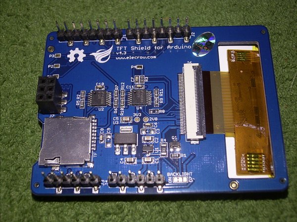
The screen can be directly fitted on a range of Arduino boards, I tested it OK on an Arduino Ethernet and a Mega2560.
Now the Nano story:
The first thing I did wrong was to connect the 6-pin SPI connector of the display to the 6-pin SPI header on the Nano. After a lot of puzzling with the diagrams and board layouts I found that the Nano has the SPI connector mirrored w.r.t. Mega, ETH, etc.
The second thing is that the SPI connector on the TFT board has no +5V and Reset implemented.
The TFT display needs the following signals: GND, +5V, Reset, Select, DataDirection, MOSI, SCK.
The Touch screen additionally needs 4 ADC channels, ADC0 through ADC3.
There is no reason to connect the MISO signal, as displays are not supposed to talk back to the application. More over, in an application where I also used ethernet I found that the MISO signal from the TFT had a bus-conflict with the Ethernet W5100 communication.
My wiring solution is in the the following diagram:
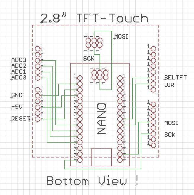
For the SCK and MOSI signals there are alternatives. If you use the connections drawn bottom right to the TFT board, then you must solder the connections labeled P1 and P3 on the TFT board. Alternatively you can use the pins on the 6-pole connectors as shown on top of the diagram.
Have fun!
A few notes per 2016-06-12
1/ In an application where I ran out of digital pins I had the temptation to use pins A6 and A7 for the touchscreen in stead of A1(XM) and A2(YP).
This will not work. Although XM and YP MUST be analog pins, they also MUST be able to be digital outputs, and A6 and A7 can only do analog.
2/ The #define's for XP, YP, XM an YM in file TFTv2.h are overruled by the file SeedTouchScreen.h in ../libraries/