Chaos Pendulum
Latest change 2023-04-30

An ordinary
single
pendulum shows a very regular behaviour, we use it in many
mechanical
clocks for pretty good timekeeping.
The behaviour of such a
system is extremely dependent on the starting condition and -as any
moment can
be regarded as the starting condition for what follows- the system will
continue to be chaotic. (*)
The
chaotic behaviour originates from the energy exchange between the main- and the second
pendulum, not
from any kind of random noise or the like.
This
pendulum is
electrically driven to compensate for the friction losses, but in such
a way
that chaos is not promoted. The main pendulum gets a push in the right
direction every time it passes the lowest point of its orbit. The
second
pendulum has no drive of its own.
This pendulum is
built
from some parts from a dismantled harddisk, the
case, the disk-motor and
the bearing of the head lever. And it took some machining of pieces aluminium I happened to have in stock.
The electrical drive is controlled by an
Arduino
Nano.
The pendulums are
not constructed as a point-mass on a thin rod, but as distributed
masses pivotted somewhere near, but absolutely not in the center of
mass. This causes the pendulums to go slower than a rod-mass combination
of comparable dimensions would do.
To make them go even slower you can position the system not vertically
but leaning backwards. This has the same effect as lowering gravity.

Download a short video of the thing moving (2 Mbytes AVI) or a longer fragment (8.5 Mb)
Probably a Matroska file works better: short video longer fragment
(*) Recently (apil 2023) there was a discussion with someone who was convinced that a pendulum like this would not behave chaoticly but would show a repeating pattern of movements. I try to prove here that that is not the case.
The reasonig goes like this:
At any moment, how infinitely short it might be, we can describe the state of the system by 4 parameters: the angles of the pendulum arms and the rotational velocities they have. All 4 these parameters can, whithin a certain range, take all possible values as in a continuum. That is approximately an infinite amount of possibilities.
Each combination of these parameters will cause a (slightly) different future for the system. In that sense the system is deterministic.
However, even the slightest variation of any of the parameters wil cause a future which will gradually differ more and more from what would happen without the variation.
My statement is now: It is thinkable, but extremely improbable that ever the exact same combination of parameter values will re-appear, which would cause a repetition of the previous pattern.
Above that: movements and turbulence in the environmental air will contribute to the unpredictability of the system's behaviour.
Mail me if you do not agree with this reasoning.
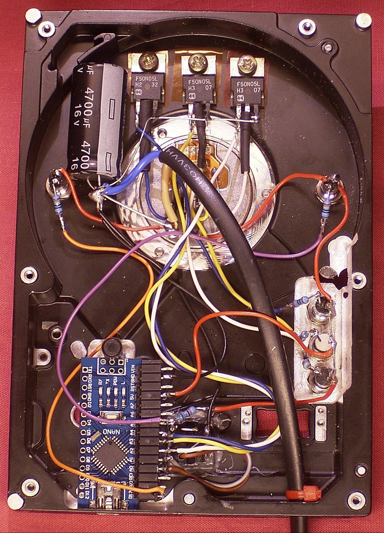
Interior. On top the power fets above the motor which protrudes out of the backside, on the lower left the Nano en
besides that the opto-interruptors. On the right the 3 leds for the phases.
Click for larger.
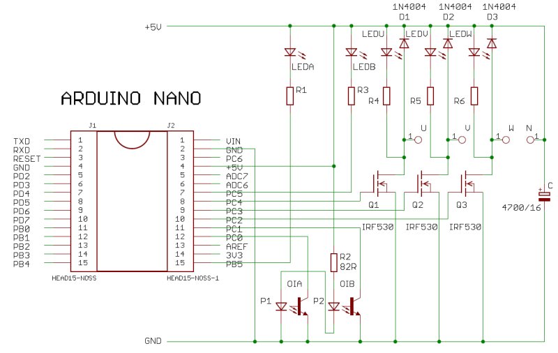
The electrical schema. None of the components is critical. Select the power FET's for gate-on threshold < 3Volts. Resistors should be chosen for suitable LED brightness. The power supply should be able to deliver 2 A minimal.
The drive control works as follows:
On both sides of the Lower Dead Point (LDP) optical shutters A and B are mounted to measure the direction and the velocity of the main pendulum when it passes. After each pass the motor is activated in the proper direction during a time which depends on the measured velocity.
The motor has 3 phases and 4 poles, so the mechanical angle between two successive phases is 30°. The angle between the shutters is 5.7°.
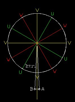
Measuring the velocity is done by sampling the optical shutters at a 4 kHz rate. During a pass we find a number of N counts for the 5.7° pass.
We activate the W-phase at 5.7 / 2 = 2.35°. Suppose that the pendulum continues at the same speed (which is not true) we should deactivate the W phase at 30°. That is N * (30 - 2.35) / 5.7 = N * 4.85 counts later. The expectation/purpose is that the pendulum accellerates during that time, so we have to switch off somewhat earlier, a factor of 4 appeared to work well. The advantage of a whole numer is also that we do not need floating point calculations.
It appeared that this way not enough energy was pumped into the system. So a second push was realized by switching on the U-phase after deactivating the W-phase. This lasts somewhat shorter, a factor of 3 * N counts works well.
When the pass is in the other direction everything goes the other way around.
Now we must take care that the pendulum does not accumulate to much energy. The indication for that is when the main pendulum makes several complete loopings in succesion in the same direction. We detect this by counting the number of passes AB and BA, and if we have seen more than X the same pass the activation of the motor is suspended. If we then see a pass in the other direction that counter is zeroed again, which releases the suspend.
X = 4 appears to work well.
We must also organize that the system starts moving, independently from where the pendulum sits still (*).The firmware can differentiate between 3 locations, on the A shutter, on the B shutter or elsewhere. For all these situations there is a test, if that position is kept to long (over 8 seconds), one of the motor phases is activated for a while. Now it could be that the pendulum sits in line with that phase, so nothing will happen. That situation is anticipated by activating another phase at the next try.
During the development serial communication has been used for diagnostics. When everything worked well this has been changed into output which can be directly used for logging in a comma separated file which can be processed further.
(*) Also during the normal chaotic movements the pendulum could come to a standstill in the upper dead point. In spite of this being an instable balance the system might stall there because of small fricton in the bearings.
Here you can download the Arduino code .