Field Mill. Latest
Change
2016-05-30


( Reactions to .... or .... You have to type this, no cut-and-paste)
In brief:
It is commonly known that we (humans) live on a magnet. The earth has a magnetic field, and we often use a magnetic compass to find our way.
Much less is known that we also live in its electrical counterpart, the dieëlectricum of a charged capacitor. The ionosphere on a height of approximately 50+ km is electrically conductive and sits on a voltage of around 300 kiloVolts. At groundlevel this results in a fine weather fieldstrength of around 200 Volt/meter. If a thunderstorm approaches or comes over this fieldstrength will dramatically change.
With a relatively simple to build instrument you can measure this fieldstrength. Here a description of such a device, and some tips to keep in mind for buildiing devices like this.
Look at a short video taken from the oscilloscope during a thunderstorm Video during Thunderstorm One can see the polarity reversal of the field.
The lower trace is a synchronisation signal.
The cracking noises are from a small medium wave radio, not tuned to any station. You only hear the flash-overs.
Contents:
Principle
Schema
Printed Circuit board
Download
Indoor Unit
Calibration
Some Tips
The principle of such a Field Mill is that an electrode is periodically shielded from- and exposed to the external electric field. This results in a small AC-voltage which can easily be measured.
First some photographs. (click on a photo for a larger version)
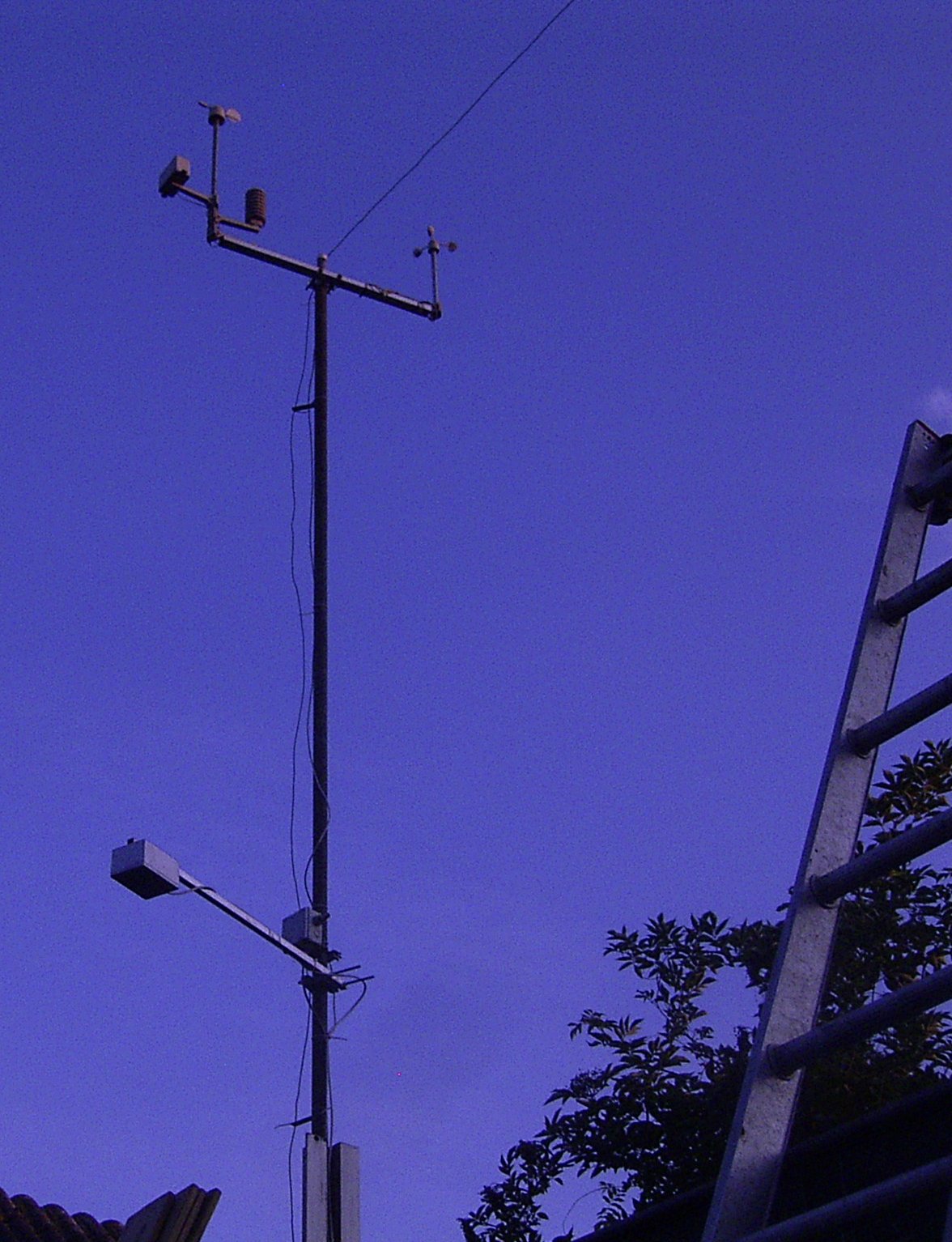
In the wheather mast. It is that little box left, quite low. It is about 2 meters above the flat roof of my shed/labo
Above that a DCF77 antenna and higher up some Alecta stuff.
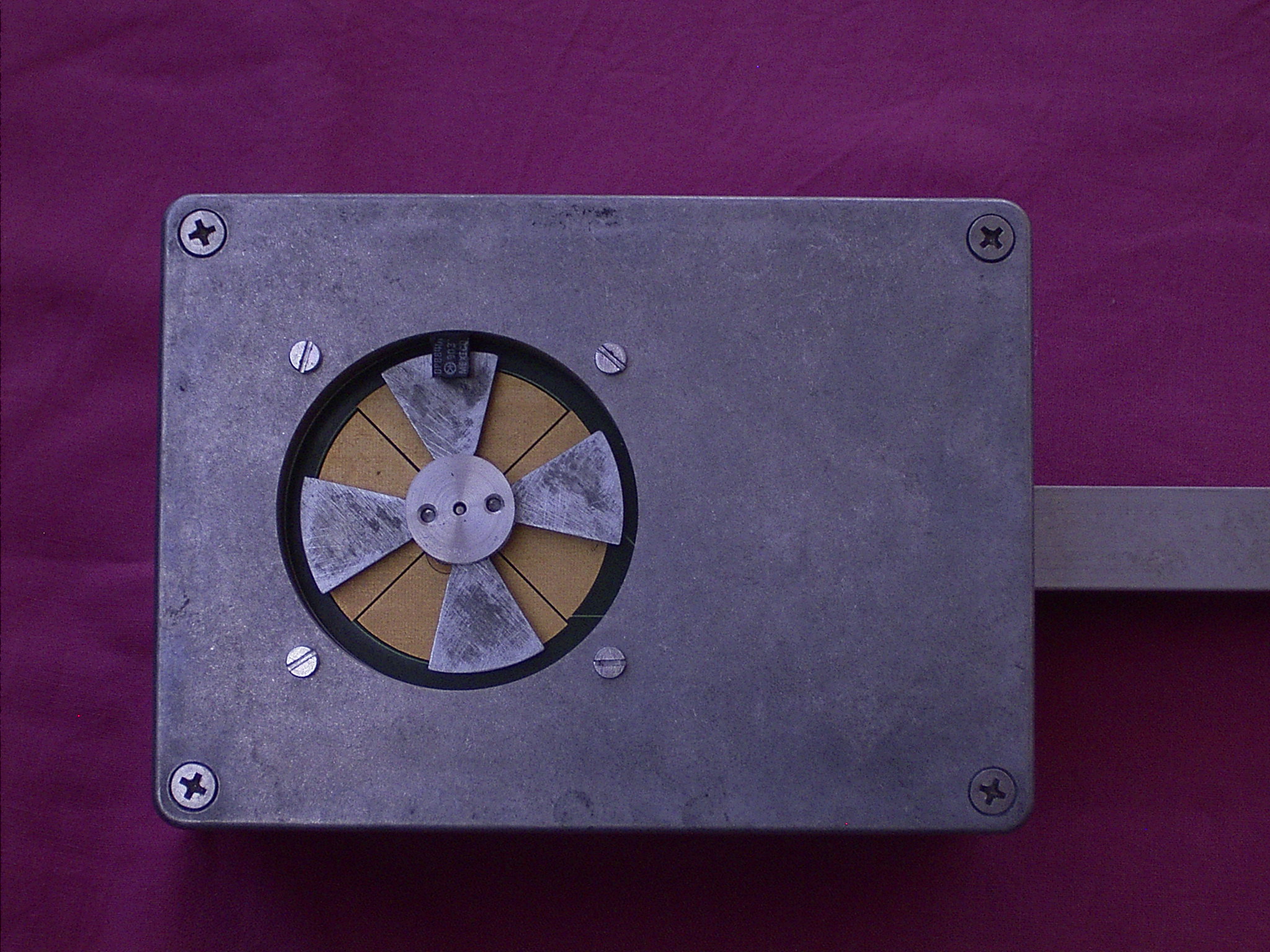
Close-up. This side looks downwards. It will also work when looking up, but than it will drown when it rains.
The case is a bare cast-aluminium box. I tried to anodize it but that did not work. We'll see how long it lasts...
You see the wings made from a plate of zinc on an aluminium pully.
In the back the gold-plated electrodes on the PCB are visible. The 8 sectors are connected every other one to the differential amplifier.
The small black thing on top is the optical sensor to determine the phase of the signal. The sensor has the emittor on the side of the PCB and the sensor on the outside. This has 2 advantages, to minimise the crosstalk from the receiver and daylight does not easily fall on the sensor. You may want to use an opto-pair with IR filter to minimise daylight effects.
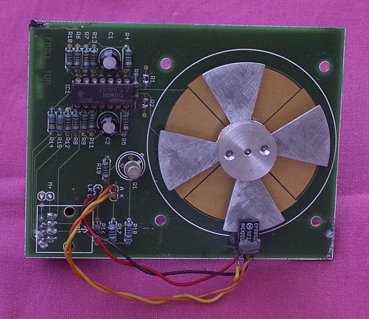
The PCB with the electronics. At the bottom near the wings sits the opto-shutter..
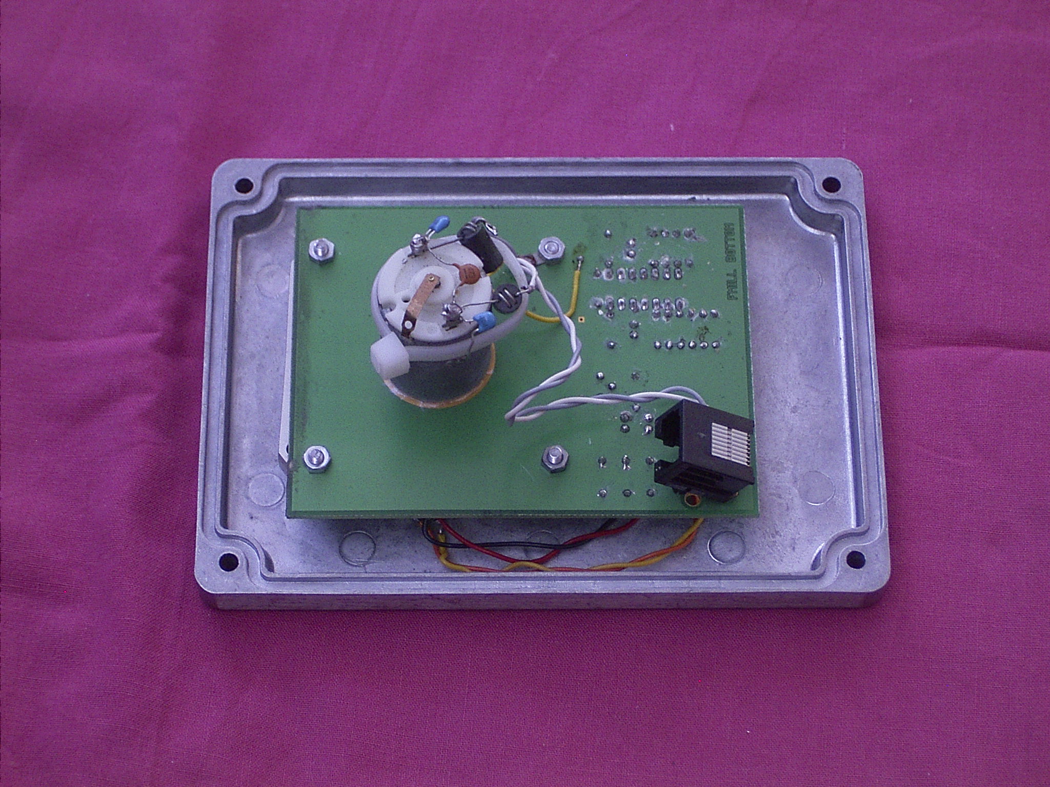
From the inside. The PCB is 2-sided with a groundplane on this side, for shielding of the electrodes.
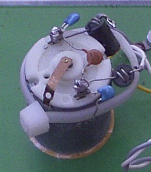
Detail of the motor, with a contact spring touching the axle. This is an absolute necessity, because when the motor rotates an oilfilm will develop (that is the essence of lubrication) which will isolate the axle so it will take the outer-world potential and the whole thing does not work anymore.
The contact spring was taken from a wrecked relay.
Be sure to select a motor which has this possibility.
The capacitors and the pig-nose inductors are mostly needed to reduce interference from the commutator.
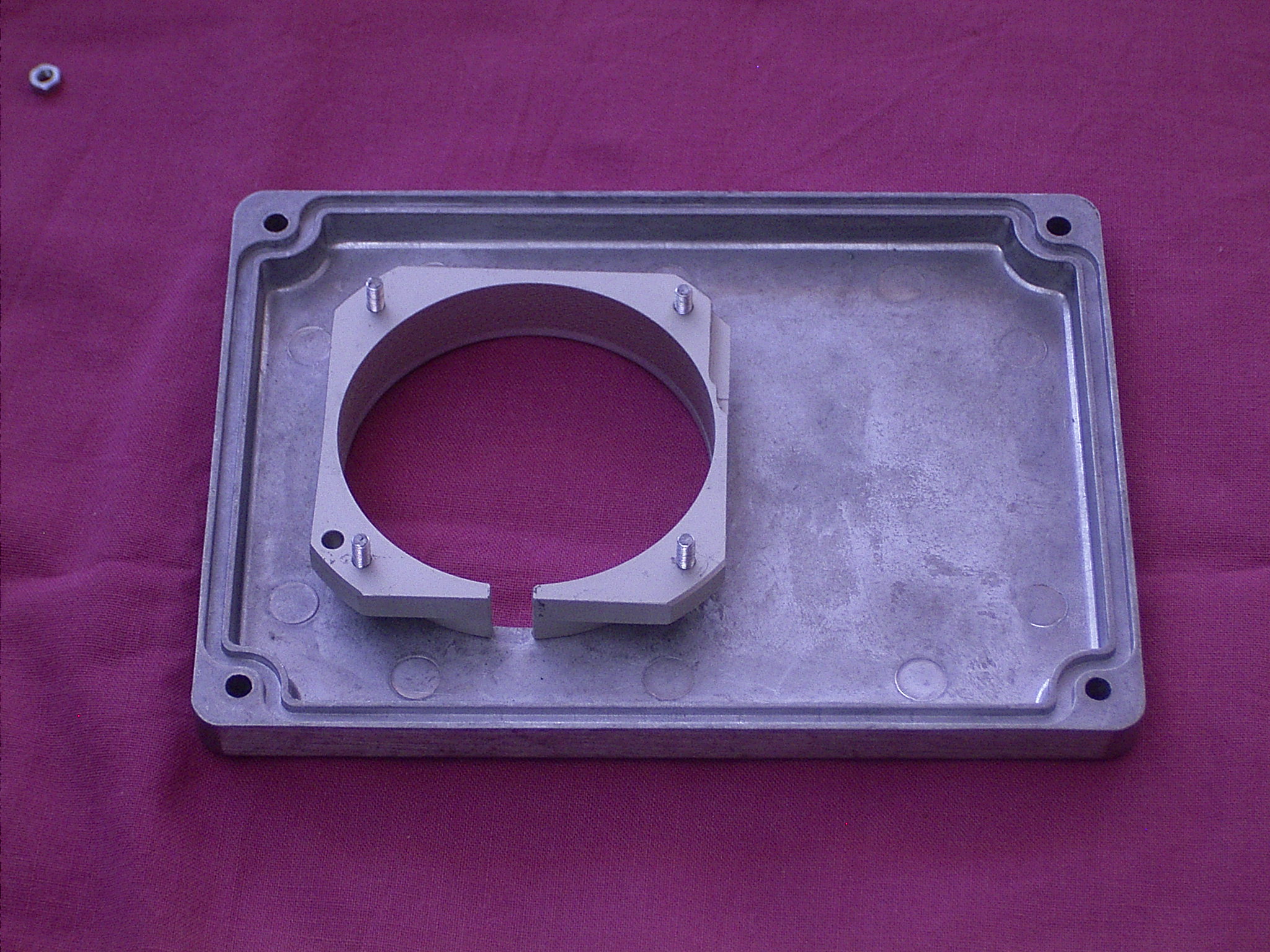
Cover with ring. I made the ring from a piece of aluminum I happend to have. (I do have some metal-working facilities)
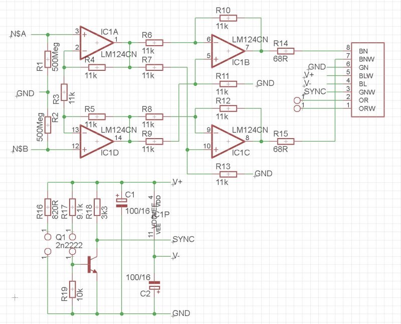
Schema of the outdoor unit.
The amplifier is fully differential, also on the output side. This prevents several interference problems.
In fact you can use nearly any quad opamp, and the 500 MegOhm resistors I used can be much lower, say 5 or 10 Meg. The input bias current will cause less problems then. Do select an opamp with high input impedance, c.q. low input bias current, e.g. a J-fet type.
As you can see the voltage gain is only 2, but that gives enough signal for most observations.
The RJ45 connector is to be mounted on the backside of the PCB.
The chopper sensor is to be connected to R16 (the LED) and R17/R19 (the sensor) The sync signal should be a rather nice rectangle signal of 12/15 Volts. Probably you have to tune some resistor values.
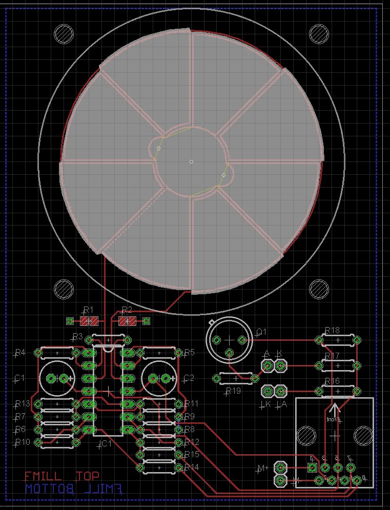
The PCB measures 76 x 100 mm and can be made or modified with the free Eagle-free version.
The motor used here has mounting holes on 14.5 mm heart distance.
Download the Eagle files, Schema, Board (probably your browser directly shows the contents, if so choose "save as" and put it somewhere you can find it back. These are Eagle 6+ files, Eagle 5 of earlier cannot read them.
Power should be + and - 12 to 15 Volts, and 2-3 Volts for the motor. Do not let it run too fast, it will wear out and make noise. Use < 50 rev/sec or < 200 Hz on the sync output.
An indoor-unit will be later designed. For the time being I use just some laboratory power supplies and an oscilloscope.
Calibration
You can calibrate the unit by setting it up outdoors. At fine wheather conditions -no clouds, no thunder thread- you will have around +200 V/meter.
More accurate, let the unit "look at" some metal plate/grid/aluminum foil which you put at a substantial DC voltage.
How to make a substantial DC voltage? Take a diode suitable for at least 800 Volts, connect it to the phase of your 230 VAC mains. This will give you 400 Volts. Put the metal plate at e.g. 50 cm distance. This will give you 800 V/meter. You may vary the distance to calibrate at different fieldstrengths and / or reverse the diode to reverse the polarity.
Be careful, this is about life treathening voltages. Us a resistor of some hundreds of kiloOhms in series with the diode to limit the current to a safer (but still uncomfortable) level.
My calibration resulted in 90 mVpp for 1300 V/m, fine wheather conditon ca. 20 mVpp
Accurate calibration is difficult, but realize that under a thunderstorm you easily find fieldstrengths of 10 - 20 kV/m, with sudden polarity reversals when a discharge takes place, also at cloud-to-cloud discharges (which are the most common.)
Use a medium-wave radio tuned to a frequency where no station transmits, to hear the crackling sounds.
Some Tips:
Do not let it run continously. It will consume energy, make noise an wear out, while most of the time there is nothing of interrest to see. Switch it on only by now and then or when a thunderstorm approaches. You may detect that by listening to crackling sounds on the radio, or by the wheather forecast.
Let it run every few days for a few minutes to see if everything is still ok.
Let the unit look down from several meters high to a surface which will not pickup an electrical charge. Plain ground is the best. The unit and its case must be connected to ground.
Up-looking or down-looking does not change the polarity of the readout! Think about that and you will understand why.
The materials I choosed may not be the best to stand and prevent corrosion. Suggestions for improvement are welcome.
Try to avoid openings in the case. Spiders and insects will find the tiniest openings and start a living inside. Periodically inspect.
From certain sources I learned that at ground-level fieldstrengths below 20 kV/m the risk of a direct hit is neglectible, but at >50: Go Inside!
(This is one of the unsolved mysteries with lightning. Discharges can take place at fieldstrengths far below the usual diëlectric strength of air, normally around 1 kV/mm or 1 MegaVolt/m. I am not a specialist in this field, I just happened to read about it.)