Water quality primarely relates to the electrical conductivity of the cooling water.
Water conductivity is expressed in μSiemens/cm. Siemens is the inverse of Ohms so 1 μS/cm means that a column of water with a cross section of 1 cm2 and a length of 1 cm has a resistance of 1 MegOhm.
Many sources of information suggest that the conductivity should be 2 μS/cm or less. At 20+ μS/cm the risk of flashing becomes serious.
I found an interresting article about the subject (throug an Israelian university site, but I could not find that back) from a french company:
Theory of Conductivity.pdf
WQ Measurement
Measuring the conductivity of the cooling water is done by a simple device consisting of two electrodes measuring 40 x 100 mm on a distance of 10 mm. The electrodes were made of FR4 PCB material with a continuous copper layer, the copper layers facing each other.
One of the electrodes is periodically (33 Hz) set to GND or +5 Volt. Just before the change we measure the current into a reference voltage of 2.5 V. From this we calculate the conductivity in μS/cm. We periodically reverse the voltage to prevent polarisation effects.
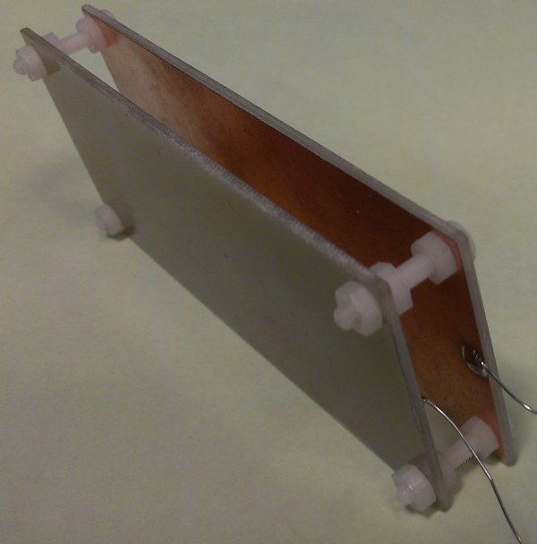
The Water Quality Probe normally hangs on its wires in the buffer vessel, completely submerged.
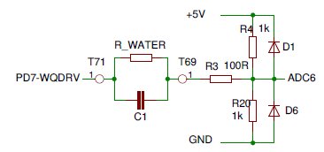
This schema is an excerpt from the SafetyBoard schema.
The probe is connected between T71 and T69, represented here as the water-resistance and an inevitable parasitic capacitance.
T71 carries a squarewave of 33 Hz, between GND and Arduino-VCC, so is on average half VCC.
R4 and R20 keep T69 also on average half-VCC, so the probe has on average no DC, which prevents polarisation effects.
R3, D1 and D6 protect the ADC input from noise spikes.
With our probe with a surface of 40 cm2 and a targeted conductivity of 2μS/cm R-Water would be 12.5 kOhm. Together with C1 estimated <= 1 nF we have a timeconstant of maximal 12.5 μsec, extremely shorter than the 30 ms measuring interval. The effect of C1 can be neglected completely.
The Arduino code handling the WQ probe is executed each 30 ms (33 Hz):
Around 5 ms before this the A/D converter was started for channel 6 and now has the conversion result ready in the register ADC:
if ((PIND & 0x80) == 0x80) WqPos = ADC; else WqNeg = ADC; // from channel 6, Water Quality
PIND = 0x80; // toggle WQDRV
WaterQuality = WqPos - WqNeg; // take pp-Voltage
As we apply a voltage of 5V-pp and we also measure the pp-voltage we may reduce the circuit to:
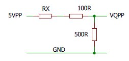
Simplified
Now VQPP = WaterQuality(ADC-value) * 5V / 1024. [Volt] (we do 10 bit conversions)
It is not difficult to see that RX = (5Volt - VQPP) * 500R - 100R. [Ohm]
The resistance of a watercolumn of 1cm2 and 1 cm length will then be RX * 40. [Ohm]
and the conductivity 1 / (RX * 40) * 10E6. [μSiemens/cm]
These calculations are done in the LaserControl Program running on the Pi.
Experiments learned that the conductivity is also quite dependent on the temperature. The lower the temperature the lower the conductivity, which is to our advantage.