The Z-axis mechanism consists of 4 M10 threaded rods on which the bed support is mounted to 4 M10 connection nuts.
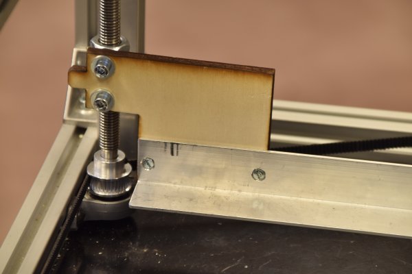
South-West corner.
The support for the bed is hanging between "ears" connected to M10 connection nuts.
The "ears" were laser cut from 6 mm thick plywood.
On the bottom we have a self-adjusting ball bearing; an identical bearing is on top, not on this picture.
Shown is a dented pully and the Z_timing belt, running across the other 3 corners.
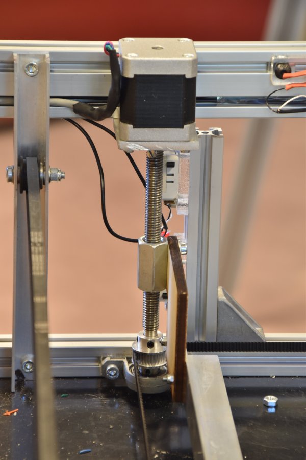
On the South-East corner we have the Z-motor in place of the upper ball bearing.
From the frontside.
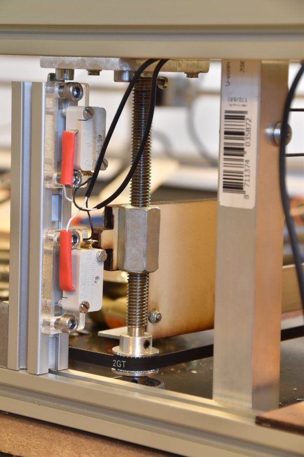
Here we have a better view on the endswitches. Note the cam on the "ear" which can hit the endswitches.
Note the acryl supports of the switches which allow adjustment in the vertical and horizontal directions.
The lower switch is the "home" switch.
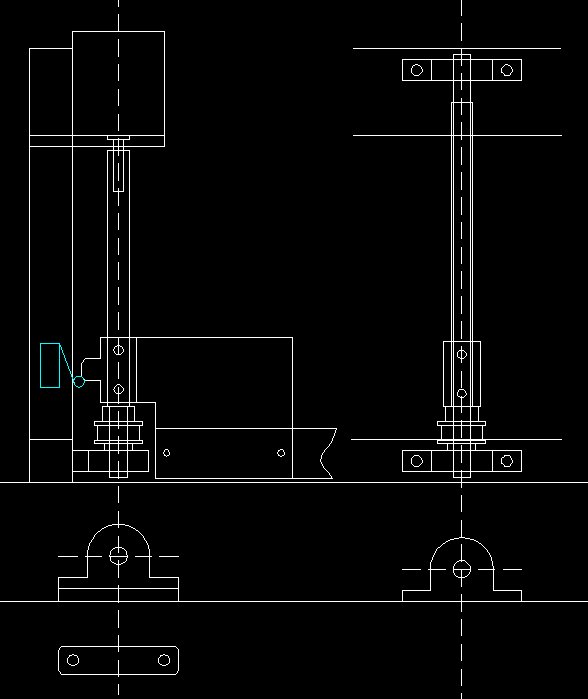
Costruction drawing.
Note that the lower bearing of the motor-rod needs an offset, because of the motor dimensions
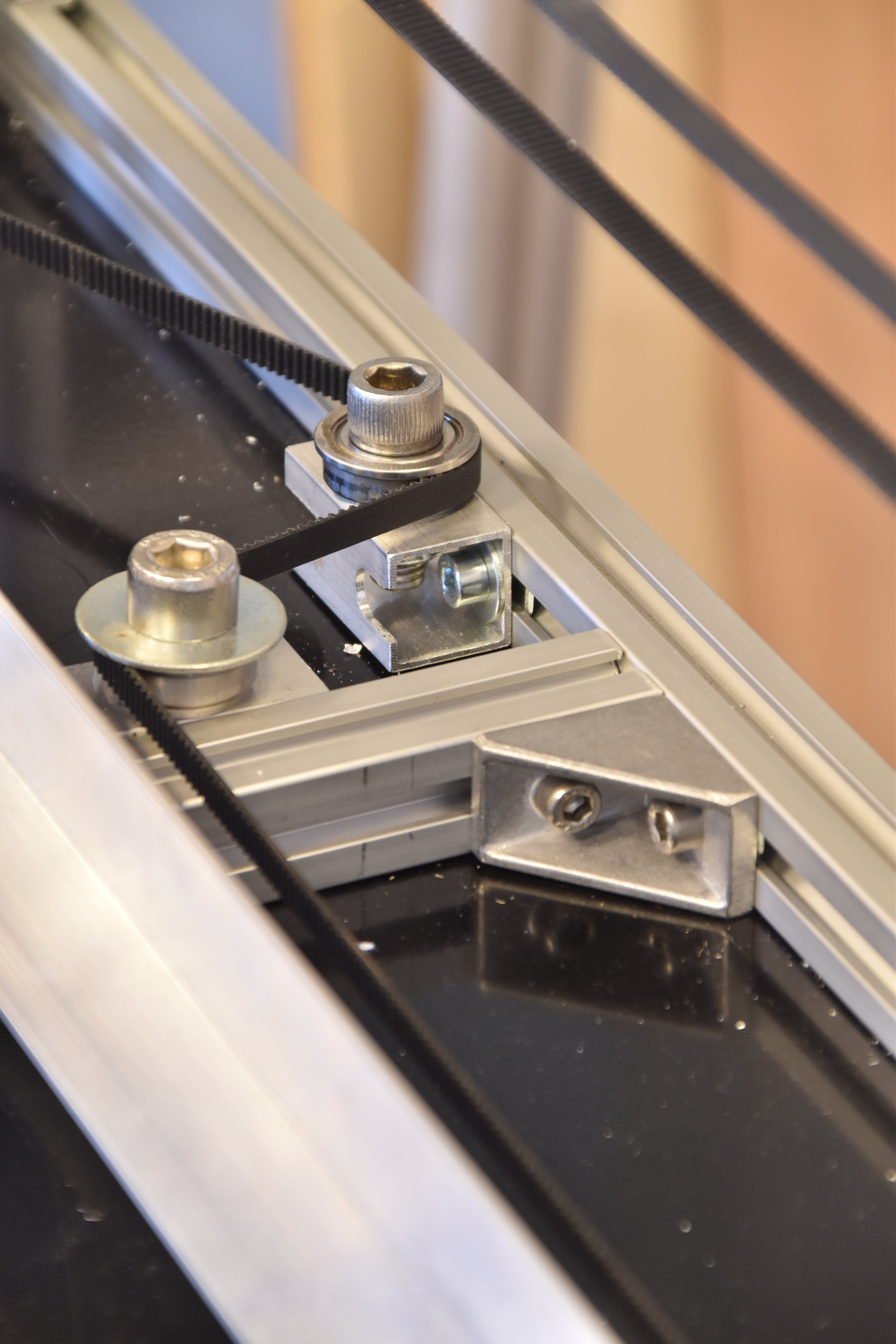
Spanners.
On the left side of the laser area sit the spanners, here seen from the back.
Two sets of ballbearings mounted to pieces of 20 x 20 x 2 mm aluminium tube with a M10 bolt and nut, and some extra rings to guide the belt.
The timing belt was made around 10 cm to long.
Making the closed belt
As the belt is going around a few times during the Z-travel we need a closed belt. We made this belt out of a 5m lengh TG2 -6mm timing belt using some specially made tools, to cut the ends of the belt under a small angle. The tools were made of some bars of aluminium ca 20 cm long.
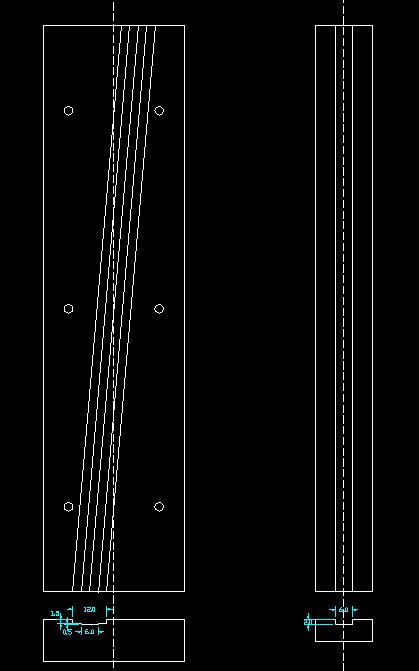 .
.On the left the tool for cutting the belt under a small angle.
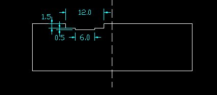
Enlargement for the important dimensions.
In the lowest groove a piece of timing belt was laid with the dents upwards. It serves to line-up the dents of the final belt.
Both ends of the final belt were laid side by side with the dents downwards, so lined-up by the lower piece of belt.
Mind the extra length needed for the oblique cut.
Then the whole thing was covered with a 2 mm thick aluminium plate.
Cutting tool, just after the cutting.
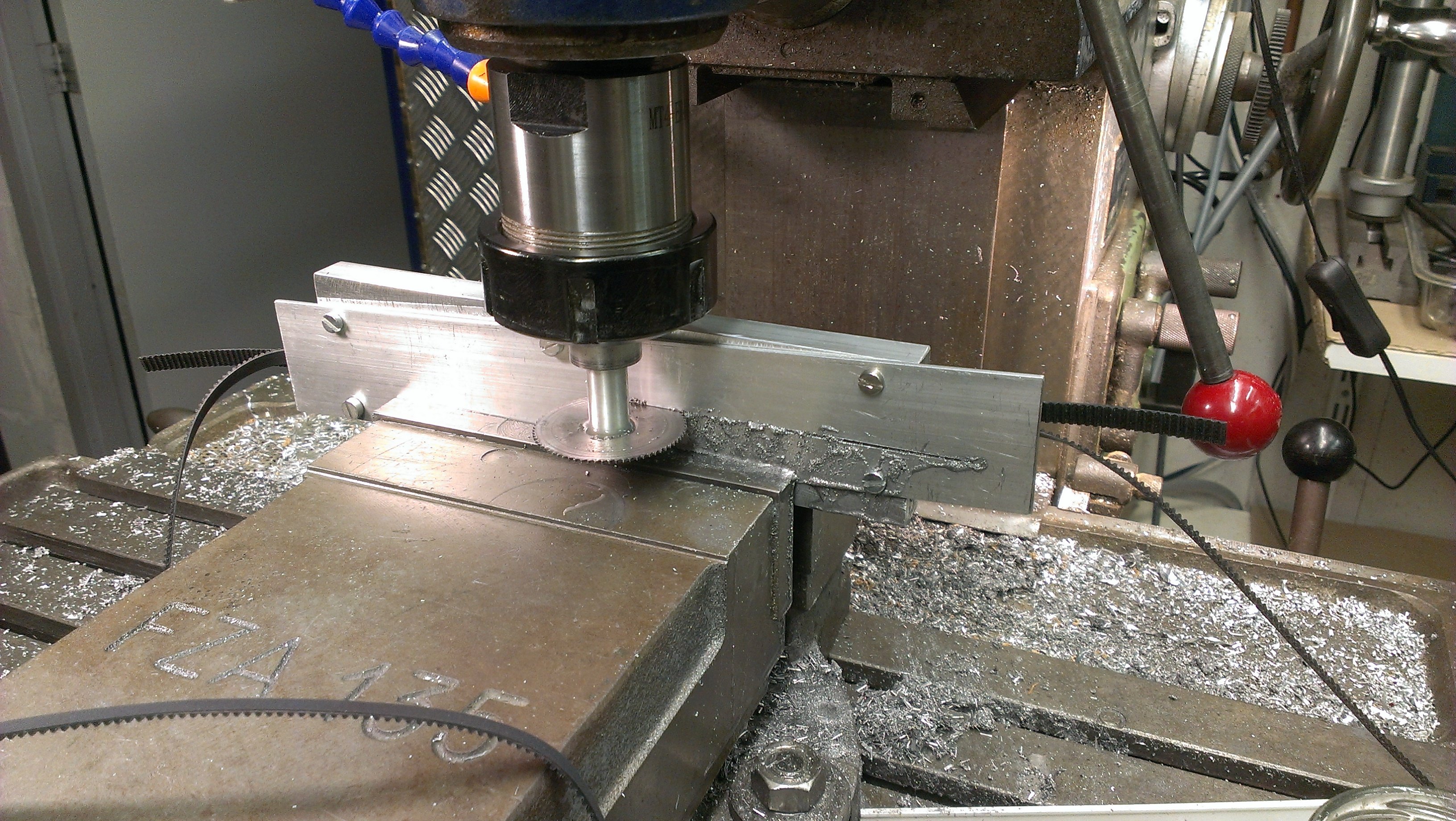
The cutting was done on the milling machine. I just cut though the aluminium and the belts.
This was the first time the tool was used, so we did not yet have a slit.
For glueing the timing belt the tool on the right side of the drawing above was used. Or one could make it on the other side of the cutting tool.
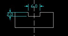
Cross section with dimensions.
Again a piece of belt was laid in the groove with the dents up, and on it the ends of the final belt, as close together as you can do it.
A piece rubber, cut out of a discarded bicycle inner tyre was used as the back-layer. Cut it oversized.
Note: you cannot use belt-material for this, the backlayer must be made of a somewhat stretchable material.
The glueing was done with Bison Kit, a contact glue based on neoprene rubber. Smear both the belt and the piece of rubber with the kit, let it dry for at least 20 minutes and then put it together. After that I applied a large force on it by putting it in the vise for several hours.
Finally cut the rubber to size with an ordinary household scissors.
Let it rest for a few days before putting tension on the belt.
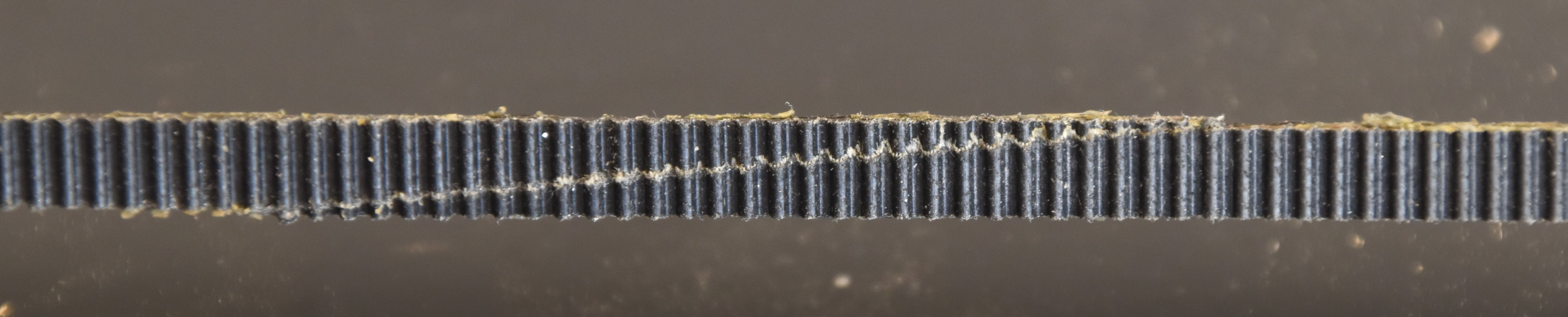
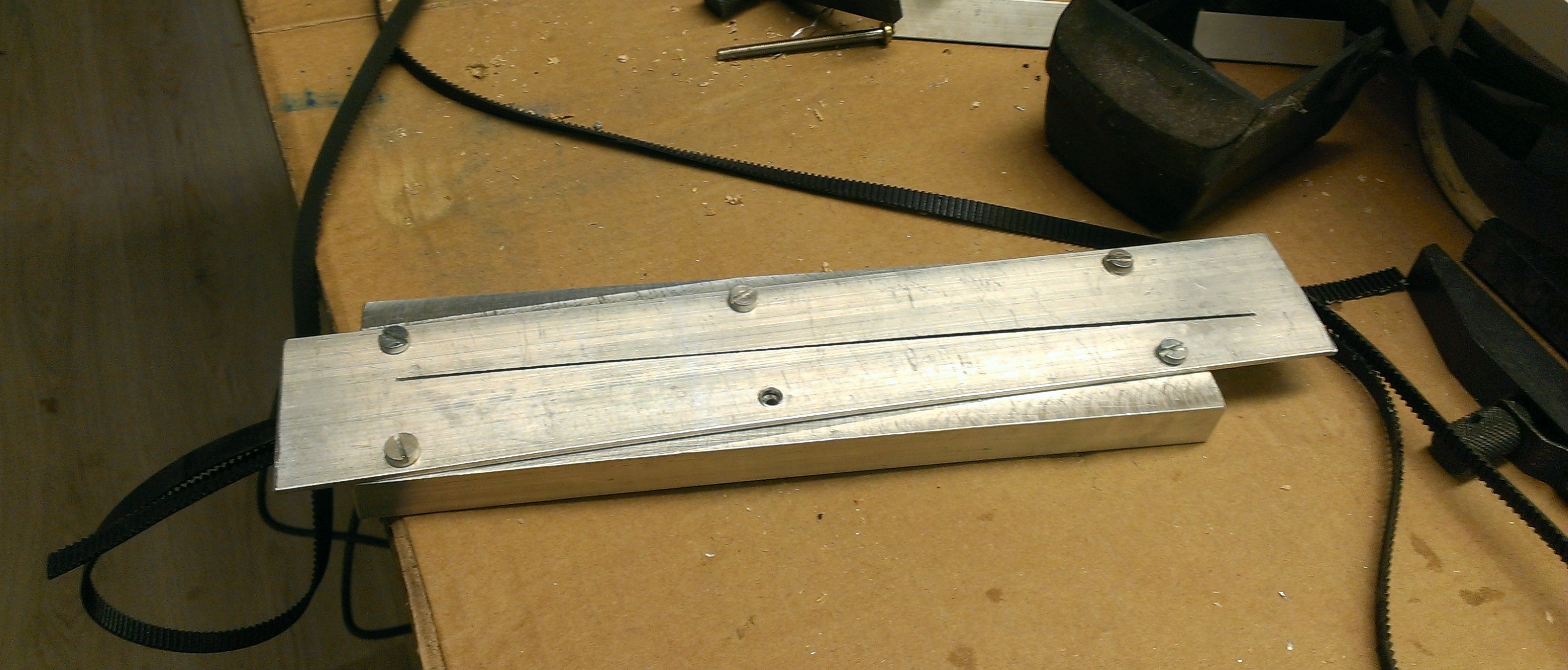
Junction
Here the oblique junction is clearly visible and the dents are neatly aligned.
When this picture was taken the belt was already for a week "on tension" in the machine, so until now we did not see any creep.
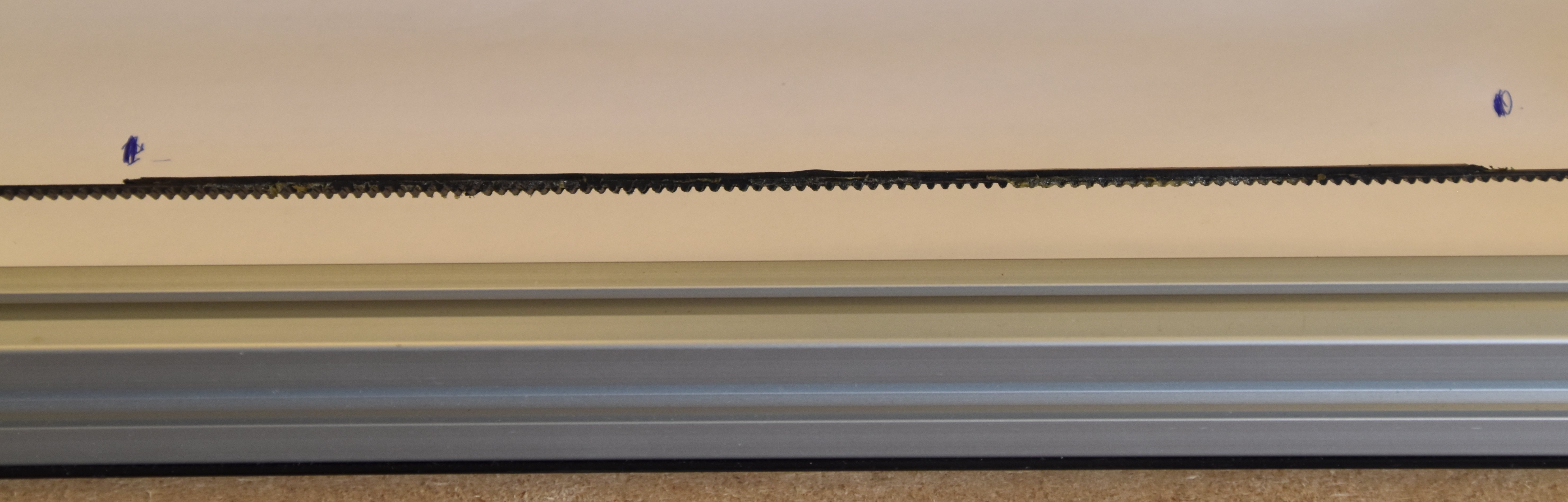
In transversal view we can see the rubber backing over an area quite longer than the junction.