In brief:
The Pendulum in the Thij-College has some interesting details .
See the PDF of the document I got from the Technical Assistent. This is a partial translation from the original document in Dutch
The interesting thing is the way the wire is suspended:
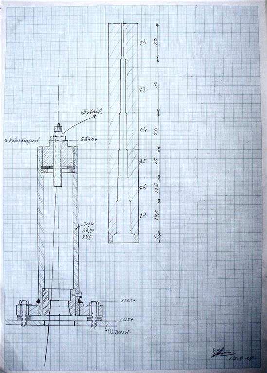
The threaded rod to which the wire is attached has a hole which widens in a few steps. The aim of the maker was to let the wire bend over an extended trajectory and ot only at the point of mounting. Because the dimensions are there I made a new drawing to scale with an extra construct in which the radial dimensions are exaggerated a factor of 10. Then Iaid the wire against the edges and constructed perpendicular lines on the midpoints of the segments, curious to see if they would cross through 1 point. They did'nt. But the fact that the pendulum effectively becomes shorter while swinging out helps perhaps in suppressing the precession of the ellips (I guess). It makes the period time less dependent of the amplitude, and that is just the mechanism which produces the ellipse-precession. If the period of the short ellipse-axis equals the period of the long axis there would be no precession anymore.
And yes, overcompensation is a possibility.
This method also works a bit as the Charron ring, the movement of the short axis encounters more friction than the long axis movement.
A full analysis of these conditions goes beyond my possibilities. I'd suggest to simulate it using a finite elements method, based on the movement equations of the pendulum.
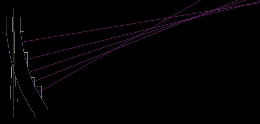
On the left side the hole is drawn, To the right the hole is exaggerated a factor of 10 for the width only, and the wire (light blue) is laid against the edges.
The purple lines are mid-orthogonal to these segments and do not cross in 1 point. However the crosspoints do come closer with larger amplitude.
Some photos I took during my visit at november 15, 2017. Click for larger.
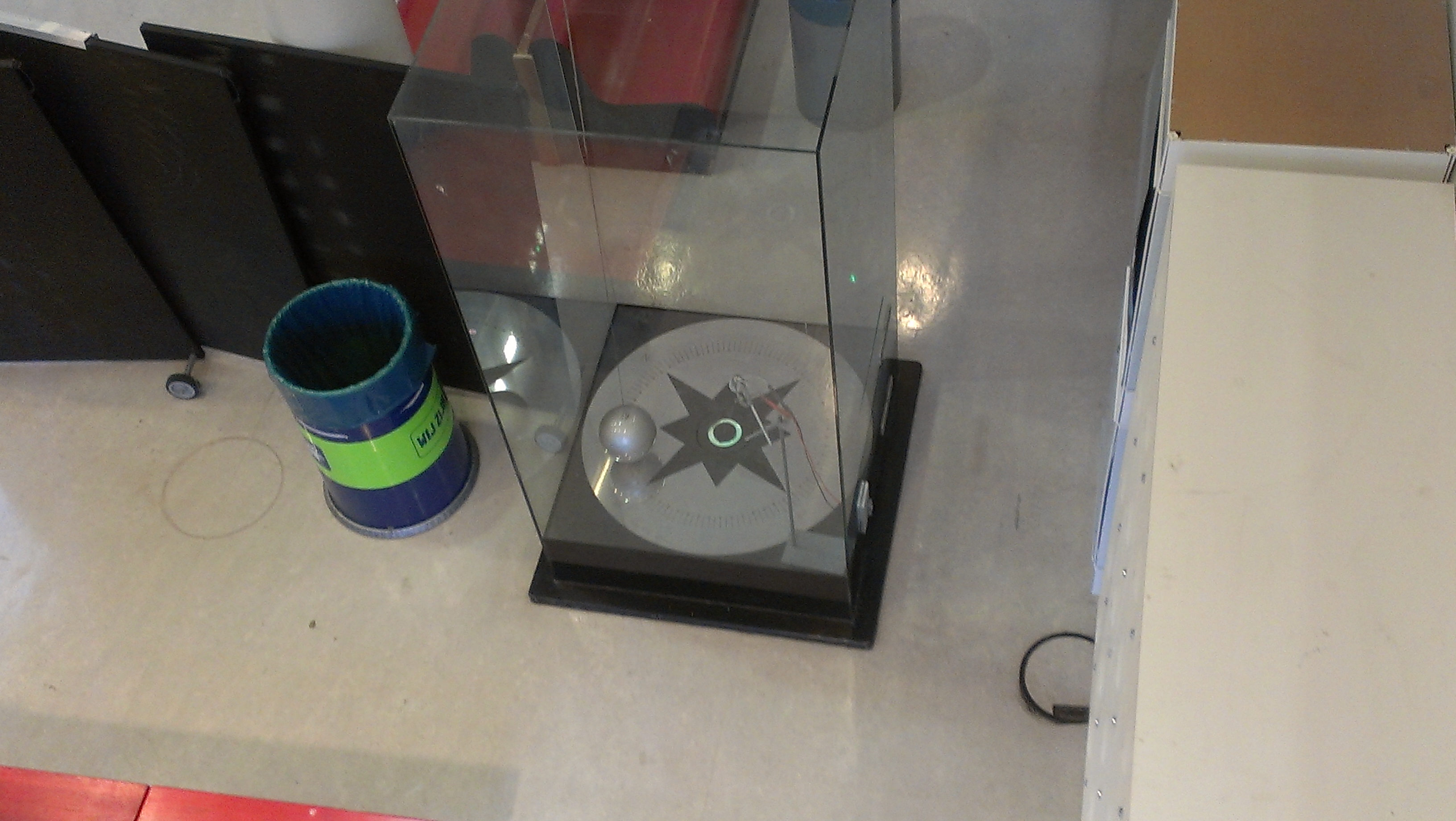
Seen from above
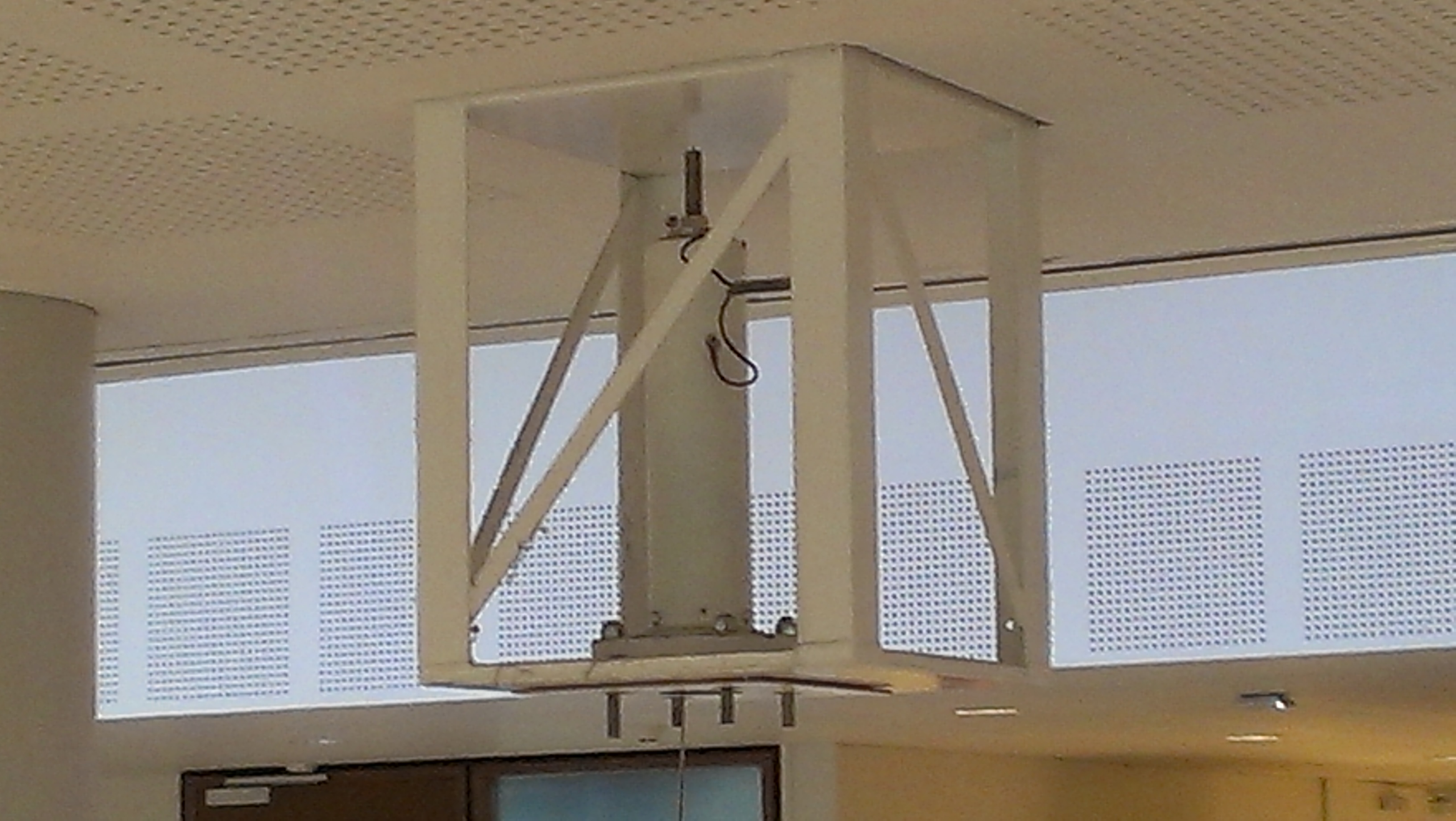
The Topmount with the tube. The electrical connections are just visible.
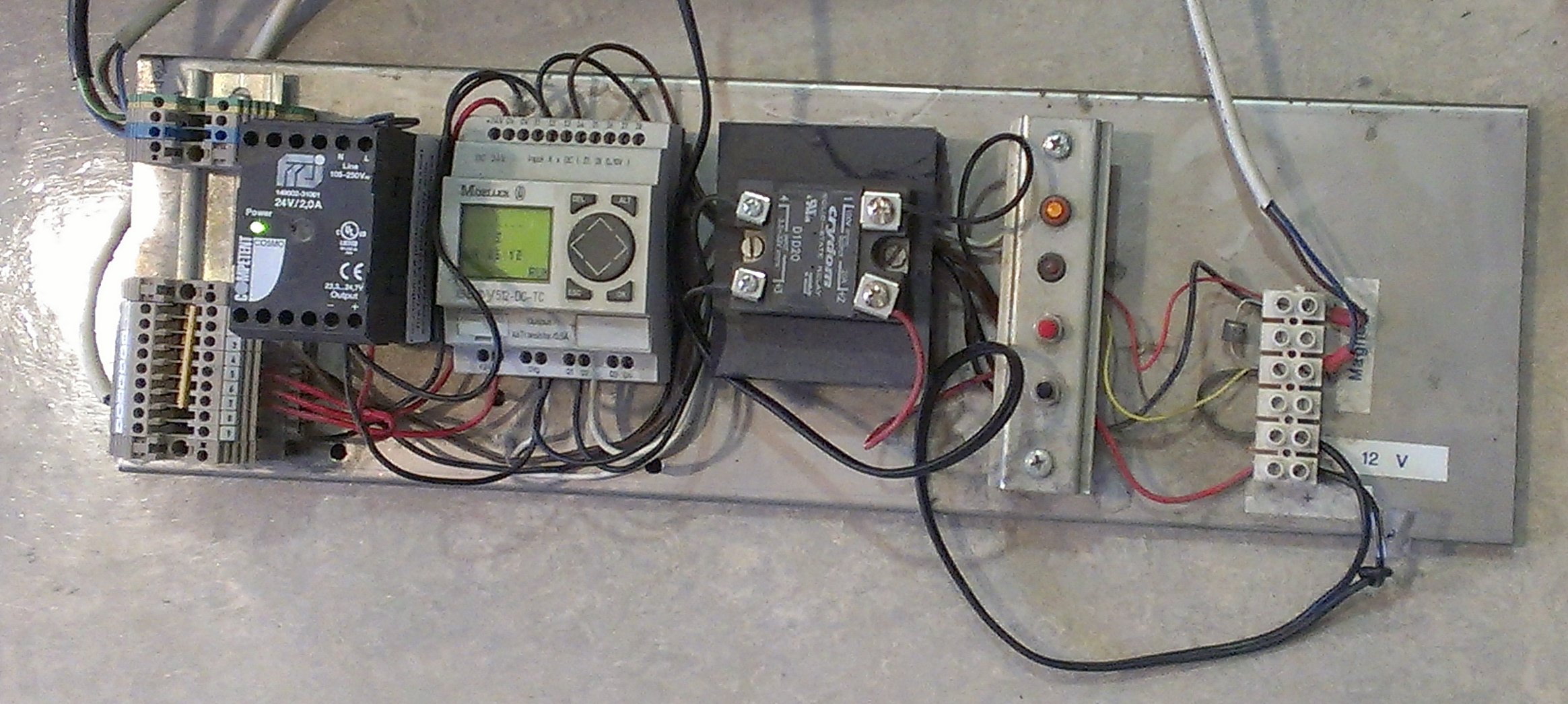
The board with the control electronics normally sits below the floorrplate.
From left to right: Terminals, Power supply 24 Volts, PLC, Solid-state switch, leds en buttons, Terminals for the electro-magnet.
The 12 Volt powersupply is not on the photo.