In brief:
There are many possibilities to suspend a pendulum. An absolute must is that the pendulum can swing freely in all directions and that the swing time is the same in all directions. That means that the pivoting point must be at the same height for all directions and should stay there during the swing.
Also the friction and the inertion must be the same in all directions.
In the early days of my experiments I tried a number of possibilities and many turned out to be inapropriate or failed after short time of service.
Universal Joint
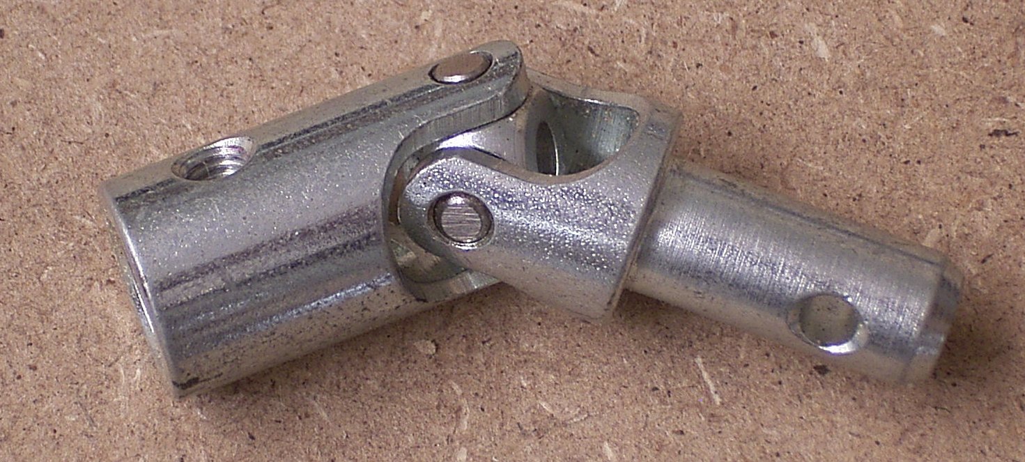
These simple universal joints ar not suitable, because there is to much play, resulting in different heights of the pivoting axes for N-S and E-W.
One-ball bearing

This bearing with 1 ball (11 mm diameter) had far to much friction. I could see that, during the swing first the cable bended, and than, suddenly the rod started moving. There may be examples with less friction, but mind the remarks about lubrication at the end of this page.
Universal Joint with ball bearings
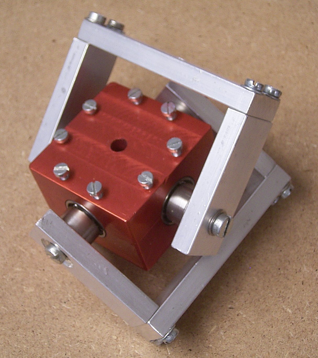
A universal joint made special for this application.
Unfortunately the holes for the roller bearings were made sligtly oversized, it shoud have been a press-fit construction. The 8 M3 screws now press the ball bearings into the right position, such that the pivoting axes are on exactly the same height.
A short test indicated however that the friction was quite high, (there was a low Q) and there was a preference for certain directions.
Probably the friction was not the same for all directions and / or the difference in inertion played a role.
Single Ball
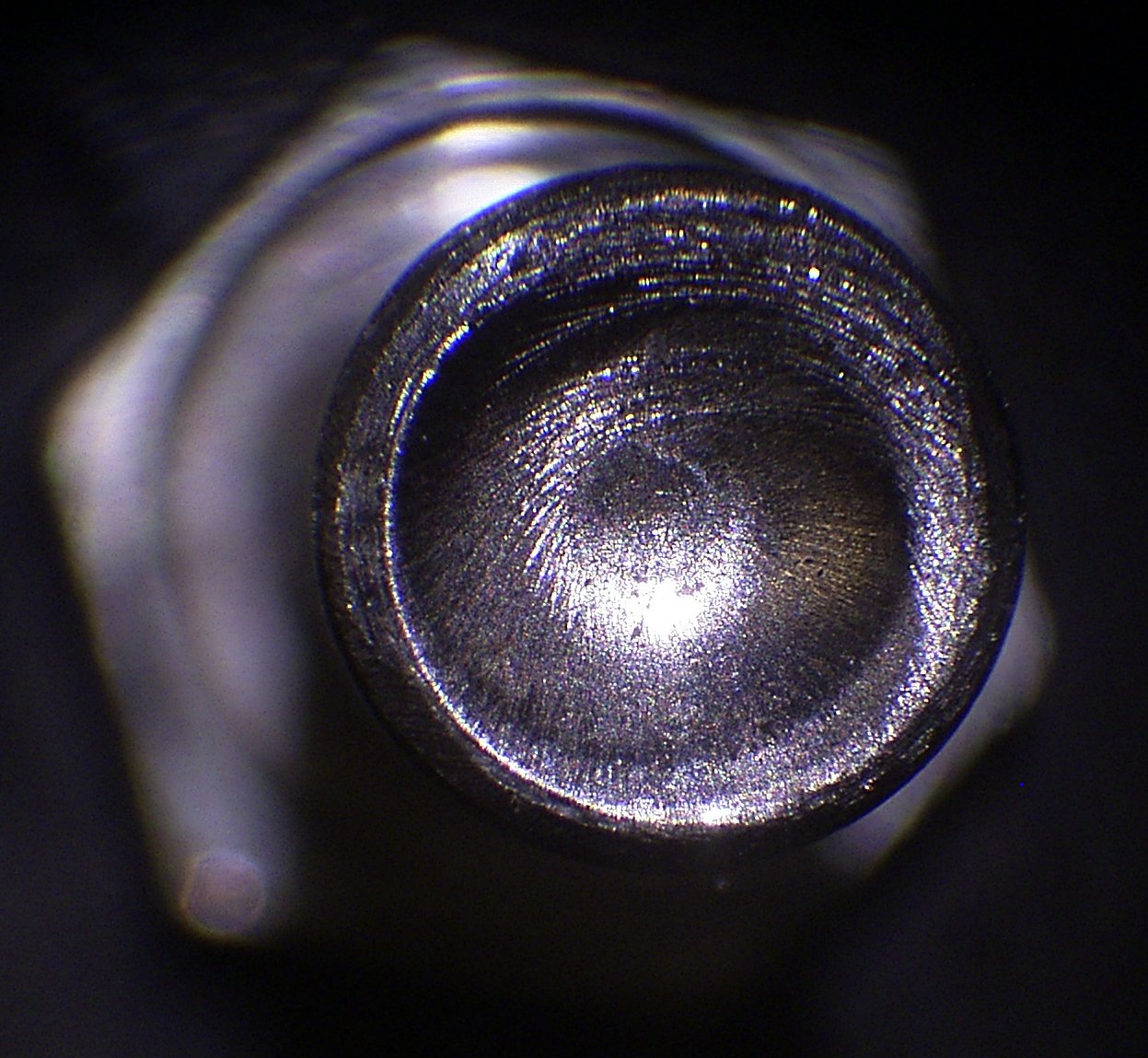
An experiment with a single ball from a bearing. A small pit was made at the end of a M6 bolt and in there a ball was laid.
After a short time of service theer was an extra pit formed by the ball.
Hardening the bolt would have been an option, but the I found a ball-tip made of glass or maybe sapphire.
See the single point bearing below.......
Single point bearing
With this single-point bearing some experiments were done, still without electical drive. Several times I have seen Foucault precession, at least a precession in the right direction and at the right velocity. Also the Q of the pendulum was measured, and it turned out to be suprisingly high. It took some 2:30 h before the amplitude was deminished to 37% of the starting value.
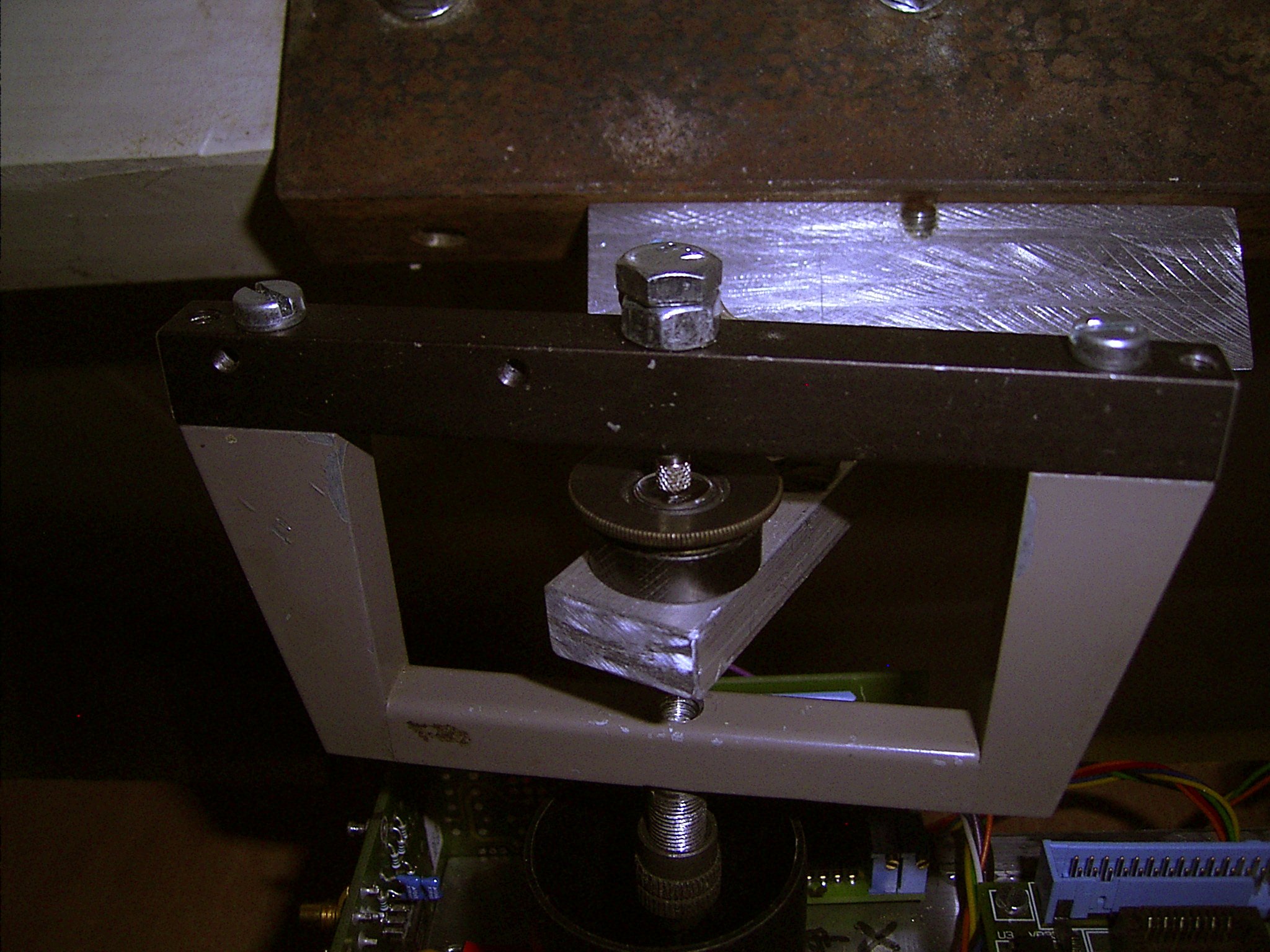
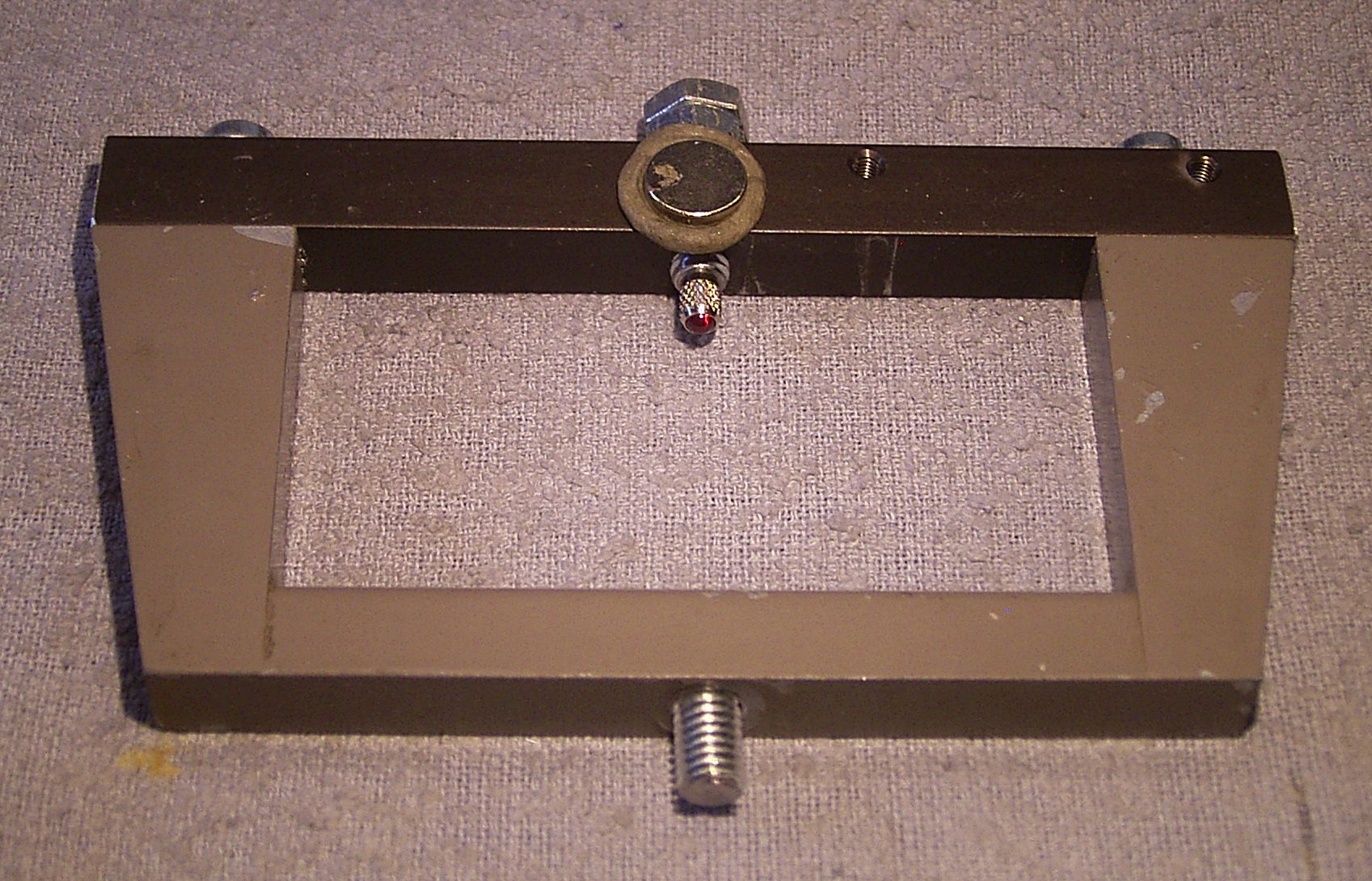
This bearing with a feeler tip and a concave piece of glass has been trie wor some time.
The thick aluminium strip is rigidly mounted to a beam in the roof of my house. On it sits a oculair with the concave lense.
The feeler is mounted to the black rod, the pendulum wire is connected to the gray handle.
Note: In this picture som electronic things are visible. In the early days I had an arrangement of two optical line sensors and leds arranged perpendicular, such that the cable made a shadow on the line sensors. With this I could measure the movements of the cable. This system was later abandoned and replaced by the magnet and Hall sensor system.
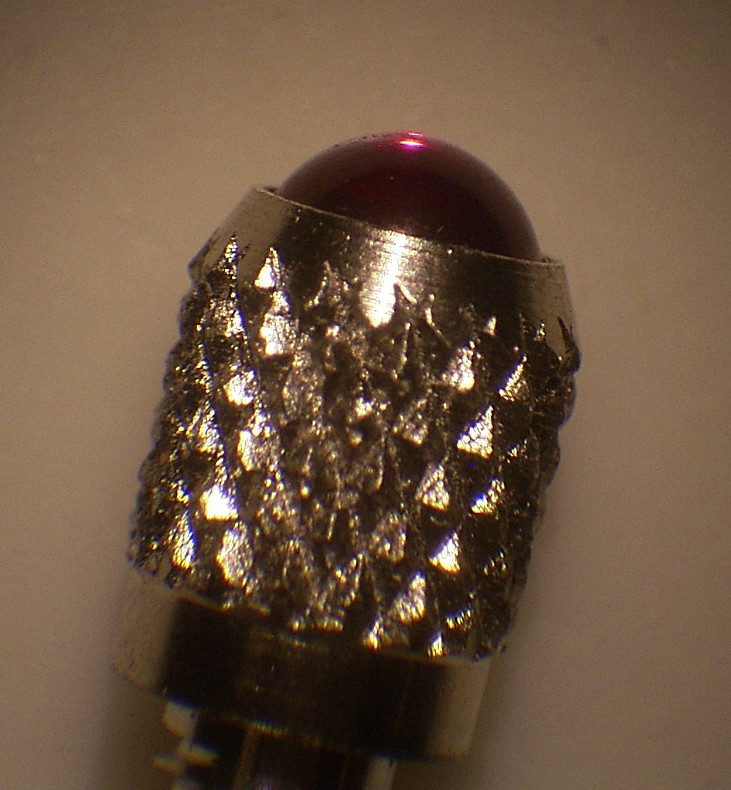
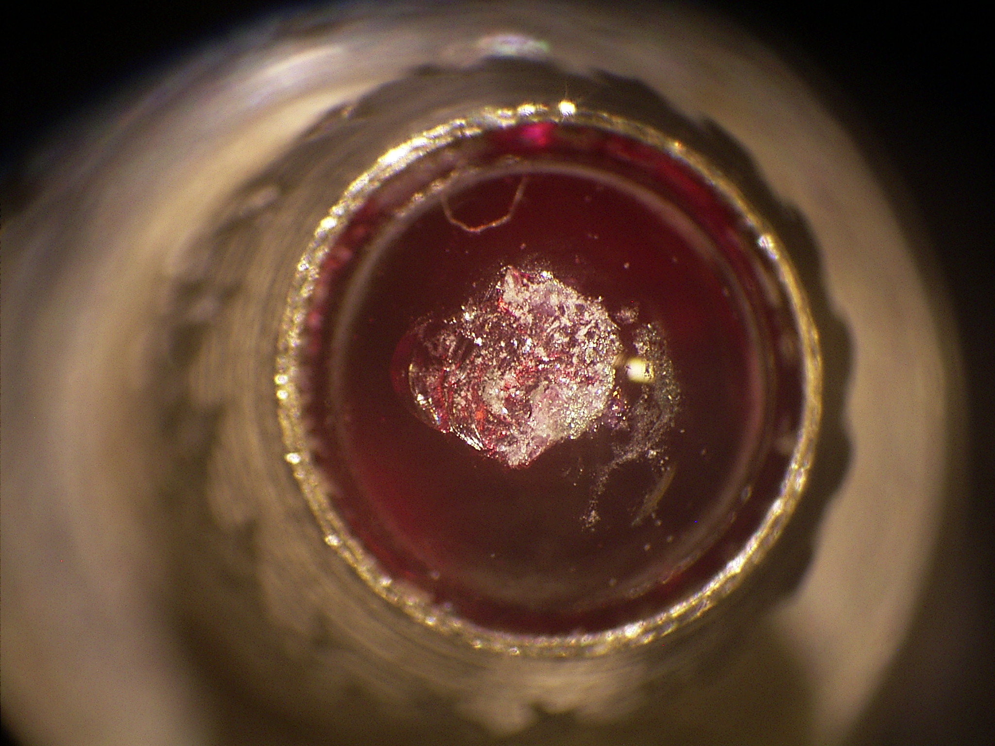
The feeler tip. The purple ball is 3 mm in diameter and probably made of sapphire or another very hard material..
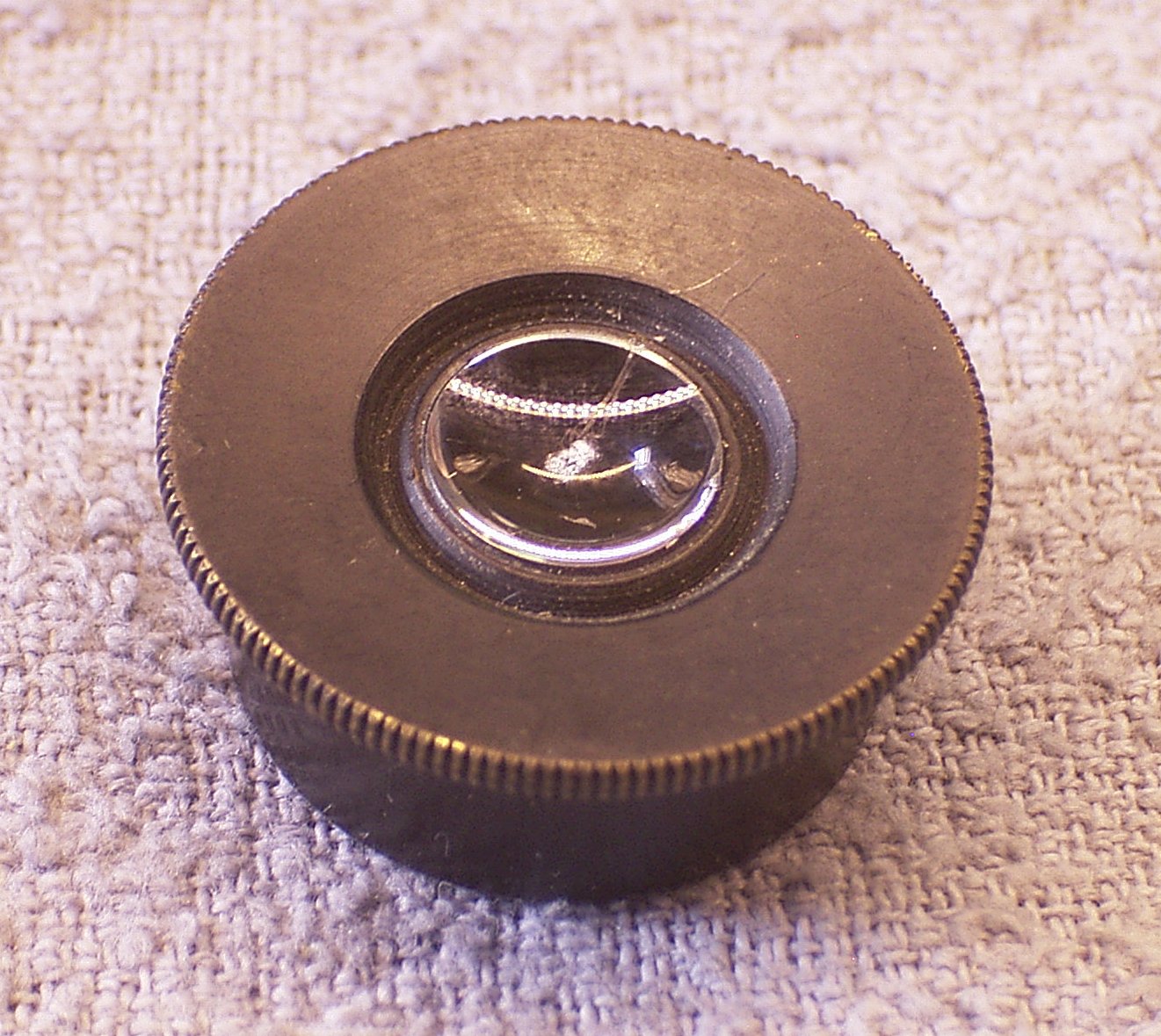
The one-point bearing rested on a piece of a microscope oculair that had a concave lens.
The handle from a 19"drawer with the point bearing.
Near the bearing point a small magnet was glued. A similar magnet was mounted on a fixed part of the construction. The attraction between the magnets should prevent the system from rotating such that the handle would touch the fixed parts of the construction.
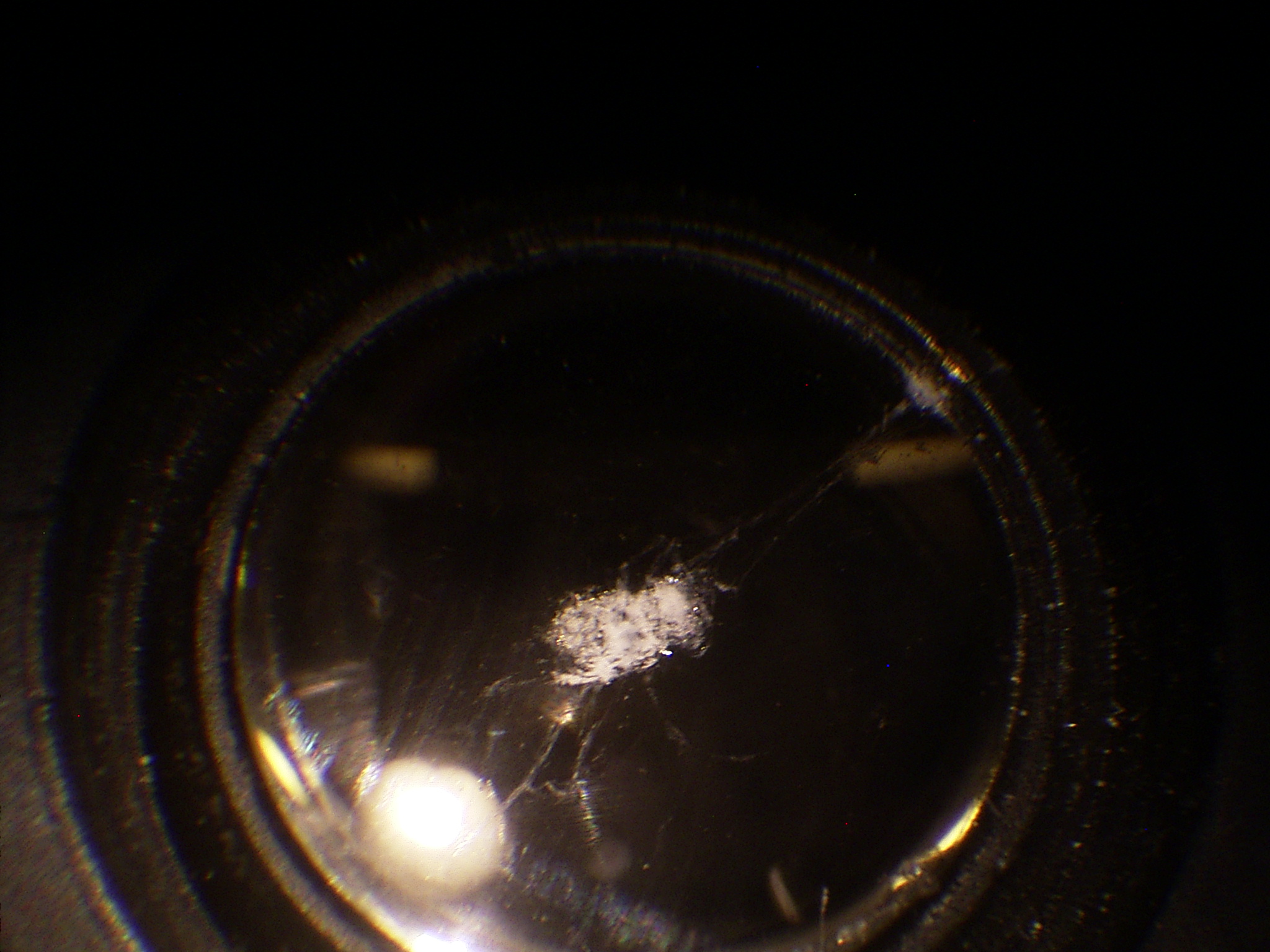
However, after not so long the lens was damaged (white spot in the middle). The feeler tip was not damaged, so must be of a much harder material.
After this I experimented with a steel plate in stead of the glass lens. A small pit was made in the steel with a bearing ball and a single stroke with a heavy hammer. After that the steel plate was hardened.
After a short time the pit was damaged, probably because a layer of carbon had formed on the steel.
Next an experiment was done with a piece of chisel steel in which a small pit was made with a Dremel diamond drill.
This also did not last, after a few days, the pendulum (still hand-launched without electrical drive) started to show strange behaviour like low and changing Q, preference for certain directions and strong oscillating ellipse forming.
Inspection of the feeler tip showed it damaged while the pit in the chisel steel was as good as undamaged.
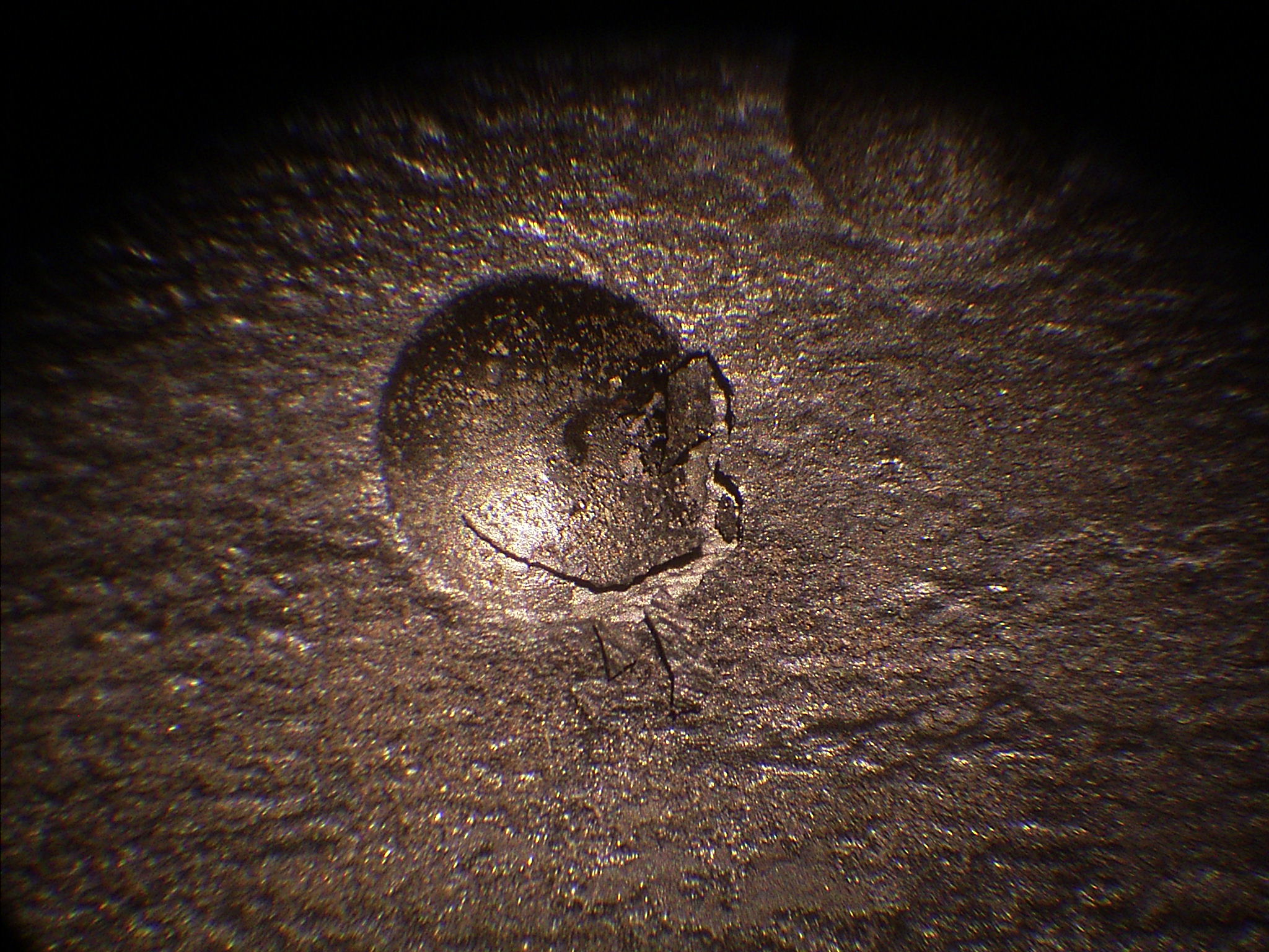
The pit in the chisel steel. ca. 2mm in diameter, made with a ball shaped diamond drill of 4 mm radius.
After launching the pendulum some 10 times some grinding grit was visible.
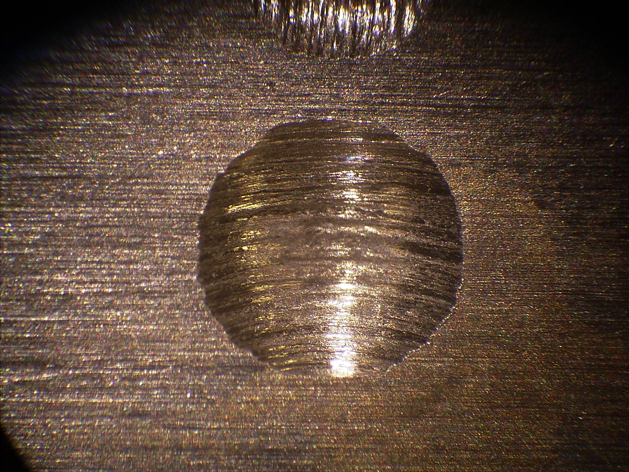
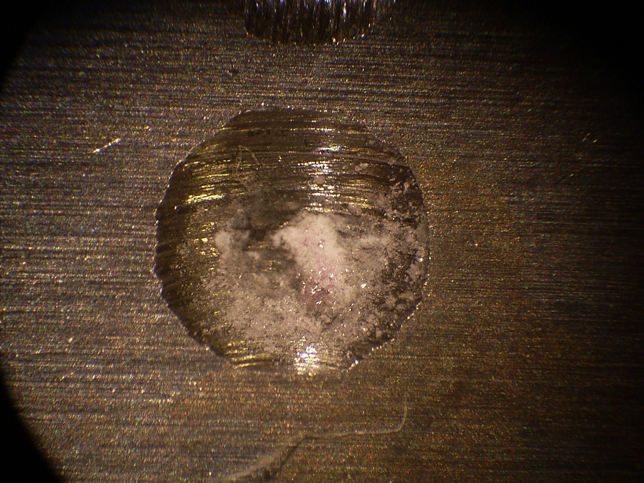
The feeler tip is damaged
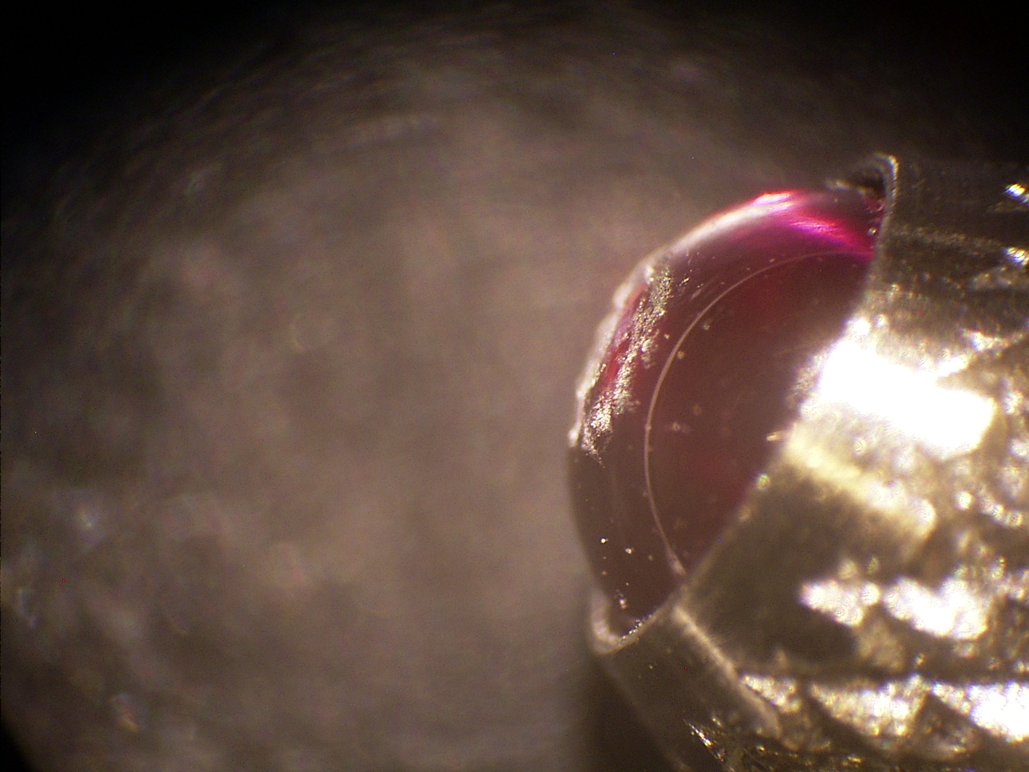
Damage seen from the side.
I have decided to do further experiemnts with a fixed wire suspension. (it is now May 2017)
Lubrication
Lubricating the bearing of a foucault pendulum often won't work well. Lubricating works by the forming of a thin layer of oil or fat such that there is no metallic contact anymore, preventing friction and hysteresis. This works well in bearings that move reasonably fast, but with the very slow movement of a foucault pendulum over a small angle the oil film will be pushed away and there will be metallic contact causing wear.
Oil or fat may surely help to prevent corrosion and dirt to enter the contact area.
Cable
All experiments until ca. may 2017 were done with a rust-free-steel cable made of 7 bundles of 7 strands each. Outer diameter 1 mm.
This cable showed certain torsion effects for which it is unclear to me if they might have influenced the results in a bad way.
Much later was found that periodic rotation of the bob around it's own axis had an effect on certain timing signals, and that this rotation could last quite long before dieing out.
An experiment was done with copper wire of 1 mm diameter. The idea was that a copper wire can be stretches quite easily bij pulling it beyond the flow limit. The wire becomes very good straight and free of internal tension. But this wire was not able to bear the bob reliably. Perhaps a thicker wire was needed.
The same was found with simple iron wire. which after pulling byond the flow limit had forgotten that it was ever rolled up.
Note: All experiments after june 2017 have been done with piano wire of 1 mm diameter in a fixed clamp at the top of the pendulum. The straight part of the cable was sometimes made of other materials, but caused no problems. See the TopMount