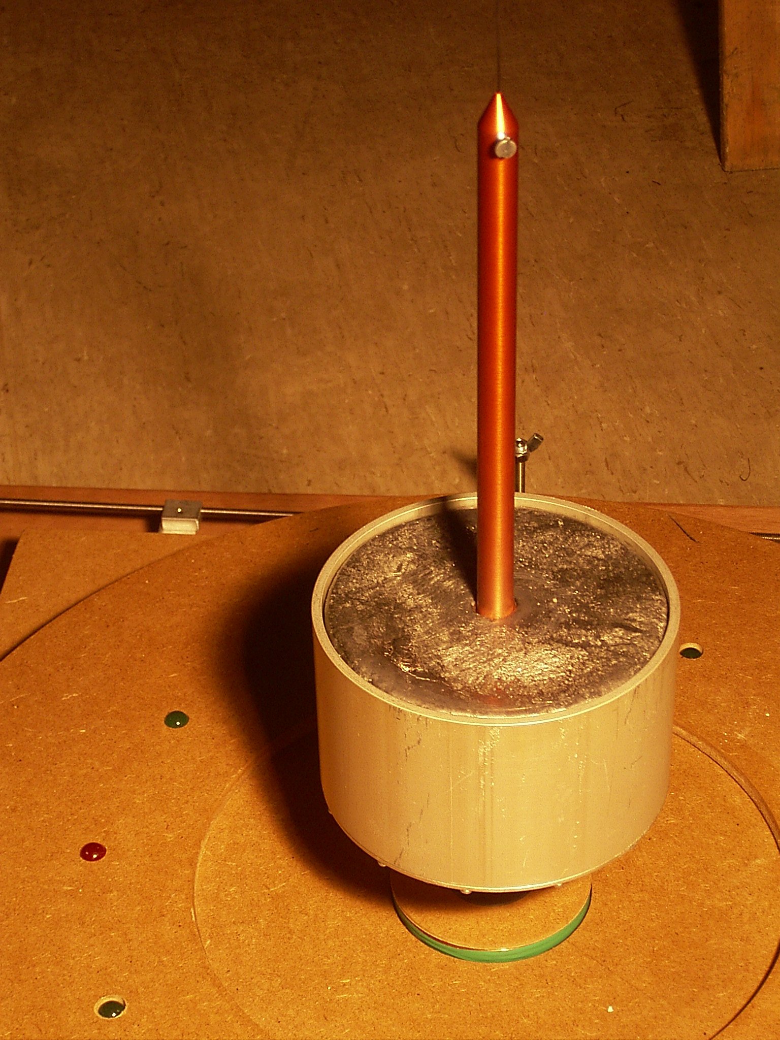
Fig 1. Bob.
The bob is constructed from a piece of aluminium tube I happened to have, with 140 mm outer diameter and 4 mm wall thickness. The tube is closed at the bottom by a circular plate mounted with 12 M2.5 screws. In the middle is a two part aluminium stem of 14 mm diameter, the lower part adapts some magnets, the upper part is mounted to the cable. The volume inside the tube is filled with lead.
In the spreadsheet is a chapter to calculate the volume and weight of this construction.
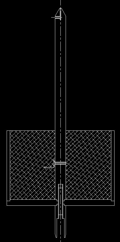
Fig 2. Cross section of the Bob.
The two parts of the stem are fixed together wit a piece of M6 threaded rod. This does not need to be non-ferromagnetic material..
The lower M3 hole's only purpose is to have a fix during anodizing the stem. It will be invisible after the lead has been poured in.
The two parts of the stem were anodized while they were mounted together, to get equal color properties.
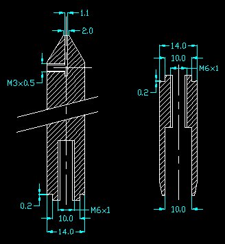
Fig 3. Details of the Bob's stem.
Note the little chambers of 0.2+ mm, they improve the perpendicularity of the bottom plate, when mounted.
Make the length and diameter of the cavity tightly fit your magnets. I use 4 Neodymium magnets of 10 mm diameter and 5 mm thickness, piled up to get a larger area of the magnetic field. The upper magnet was fixed with a little bit of 2-components glue. The others will stay together by their magnetic fields.
Be sure that the hole in the lower stem part goes through. That allows you to push the magnets out if necessary.
Make the hole in the top of the upper stem fit your wire.
The wire was fixed with a short M3 imbus screw with a blunt top which does not nick the wire. This happened to be insufficient, the 13 kg Bob slipped from the wire. So I changed the construction a little bit.
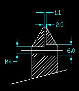
Fig 4. Improved wirefix.
The M4 screw (not drawn) will bend the wire into the 6 mm hole.
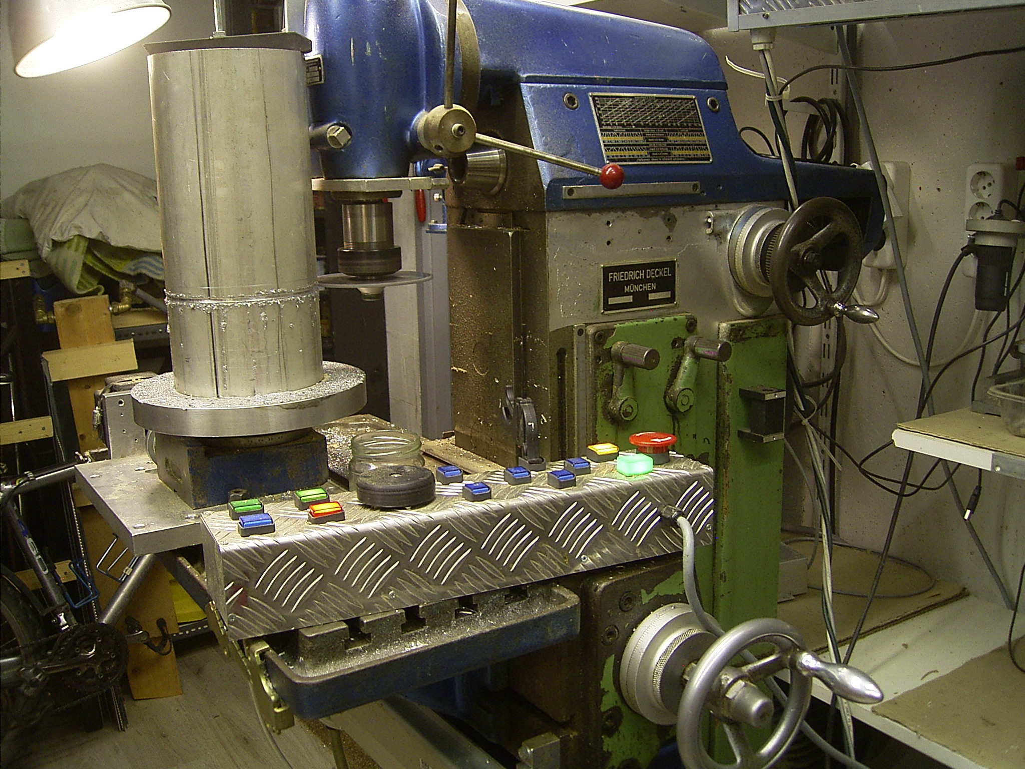
Fig 5.
Cutting the Bob's shell on the milling machine using the motor driven rotary table.
I first made a wooden disk to exactly fit inside the aluminium cylinder.
Then the cylinder was put over the disk so it was centered well and I fixed it with a long central threaded rod.
I did not cut it through completely because then the fixing would be gone, the last cutting was done by hand.
The edges of the Bob's cylinder could be finished on the lathe, and the holes for the M2.5 screws were made on the milling machine again, centered by the wooden disk, and with the bottom cover in place to have the holes match exactly.
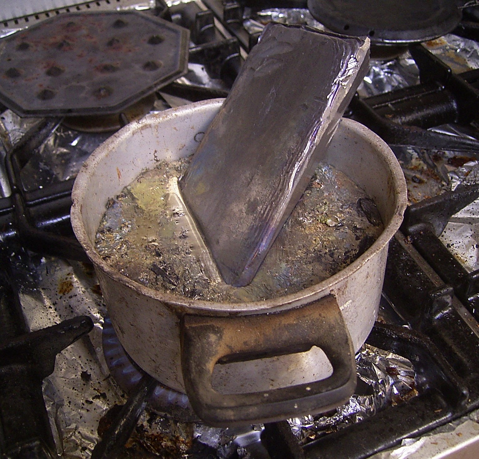
Fig 6. Melting lead on the kitchen gas.
It probably won't work with an electrical or induction cooking plate. The plate may even be damaged by the high temperature required. (330+ °C).
Be aware of the weight of such a meal. I used two pipewrenches to grip the pan for pouring the lead into the bob.
Replace the lower stem with a M6 screw and washer so the bob casing kan stand safely.
Magnets in the lower stem will not survive the heat of 330+ °C.
Do not heat the lead in the Bob's shell. It will leak out like water through the tiniest opening. Pour the lead into the cold shell, it will solidify before leaking out.
Buy the lead in a shop for (sail) boat accesories. There it is often used as ballast. The roof lead in the DIY shop is probalbly much more expensive.