The diemnsions here are for the coil set in the Vrijland experiment.
Center coil
Drive coil
Rim coil
Coil support
Assembly
Photos
Center coil
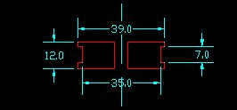
Do not make your center coil to small in diameter. When the pendulum develops an elliptical path it might miss the center coil completely.
The center hole was only used to mount the workpiece on the lathe.
Drive coil
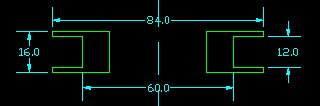
The center hole should accomodate the Center coil with a little bit of pressure.
Determinig the diameter of the drive coil requires knowledge about where in the swing the drive pulse must be given, according to the Schumacher principle. See Ellipse, Schumacher. So, if possible, construct and (temporarely) mount your bob first to do a Q-measurement. Then use the spreadsheet to estimate the radius of the Drive Coil.
I made the drive coil from 15mm thick MDF, but any stiff insulating material can be used.
It is not a bad idea to include an auto-resetting thermal fuse. In case of a defect in the electronics the coil might stay engaged for long time, which at least will smell, and probably may cause a fire hazard. A properly dimensioned PTC (resistor with a steep Positive Thermal Coefficient) may also work.
Rim coil
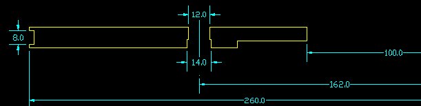
Dimensions are radii from the centerline right, not visible.
The 12 mm holes allowed mounting of Led's which flash at each center pass of the Bob. Not used anymore.
The Rim Coil has an effective diameter of 53 cm and 380 turns of 0.125 mm wire.
Measured resistance is 926 Ohm, measured self-inductance is 320 mH.
Coil Support
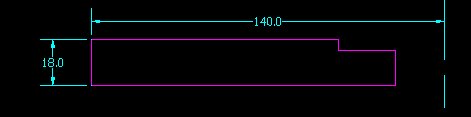
The coil support itself rests on 3 metal pins on the Floorunit. The metal pins are on the same diameter, but not 120 degrees apart, so it will fit only in one orientation and can be removed and replaced very accurately. Washers around the pins allow space for the flatcable to come out. In the upper plate of the floor unit is a hole to have space for the Junction Board.
Assembly

The Drive- and Centercoils fit in the coil support plate (purple), the Rim coil fits over the support plate and ens up somewhat higher.
Photos
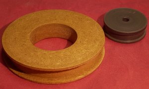
The bare coilformers of Center and Drive coils.
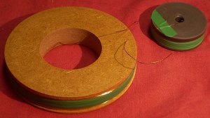
After winding.
This is the bottomside where the wires come out through small holes.