Laser Power Supply Instructions HVPSU Manufacturers wesite (we have the X3 model)
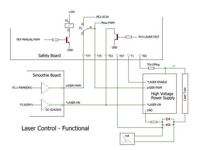
Laser Interface Functional.
The signal LaserEnable is given by the SFB when all conditions are such that the CO2 tube can be operated safely. In particular when the waterflow is to low the LaserEnable signal will be inactive (high).
The signal LaserON origines on the SMB, SFB "listens along" to determine the laser-On time for accounting, but the SFB can also switch the laser on for test-shooting. For this we have the "wired or" function with the open collector drivers.
The laser power % is controlled by a PWM signal from the SMB to have the laser intensity modulated by the job. Alternatively the power % can be adjusted by hand on the console. For that the relay K1 is activated and a locally generated PWM signal is sent to the HVPSU. The indicator on the GUI always shows the actual PWM% which goes to the HVPSU.
The actual voltage on the CO2 tube is measured with a voltage divider of 700 MegOhm to 100 kOhm, giving a range of 35 kV with the ADC range of 5 Volt.
The current through the CO2 tube is indicated by the mA meter on the console, protected with 2 diodes, and measured on the SFB with the shunt resistor. of 140 Ohm giving a range of 35 mA. The shunt resistor and the diodes are located very close to the HVPSU so there is little risk of getting a loose wire with heavy sparking in the middle of the elecronics compartment.
Also see the signal descriptions for the Safety Board.
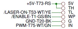
Signal connections to the HVPSU.
HighVoltage Circuit.
To allow us to measure the actual voltage on the tube we need a 3-way coupler suitable for this high voltage.
It was made from a piece of acrylic material 25 x 25 x 60 mm I happened to have in stock.
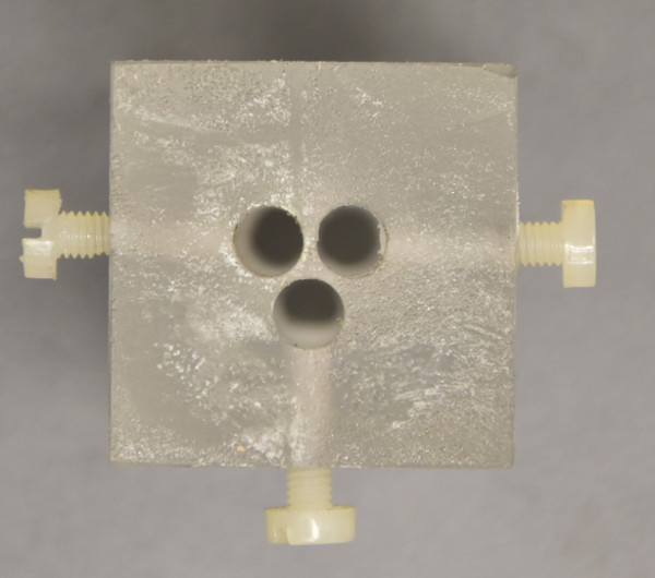
High Voltage Connector.
From the top 3 wires can be inserted and fixed with nylon screws.
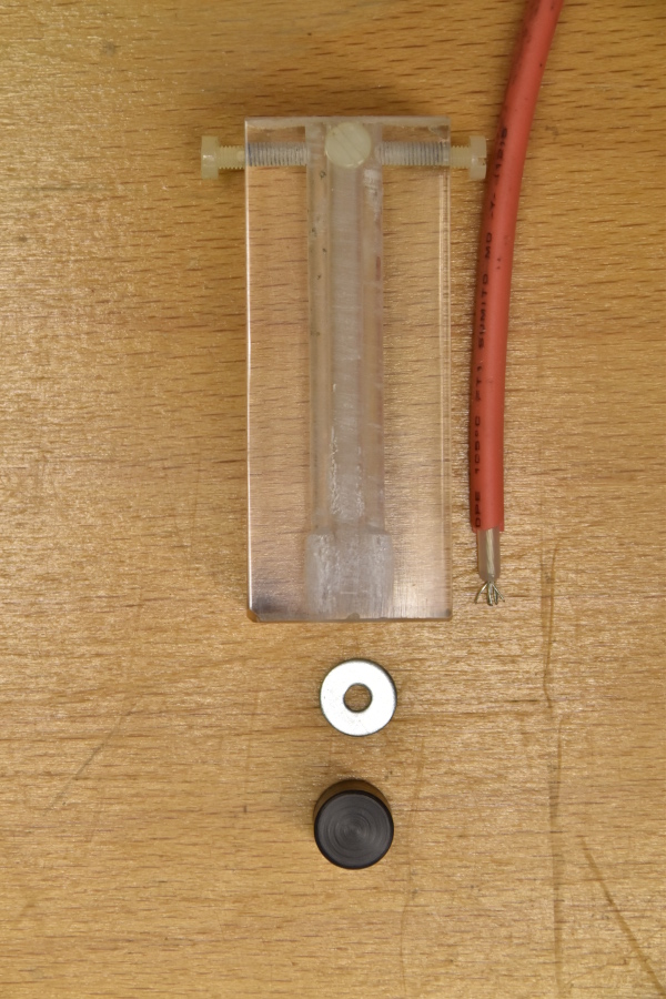
High Voltage Connector before assembling.
About 10 mm from the bottom the wires are electrically connected together by a metal ring.
The opening through which the ring is inserted will be closed by the black cylinder (POM) wetted with 2-component glue.
As POM is hard to glue I made several grooves in it to increase the surface area and make it unlikely to fall out or to allow sparks to expell.
The wires will be insrted after slightly wetting with white vaseline (pure petroleum yelly)
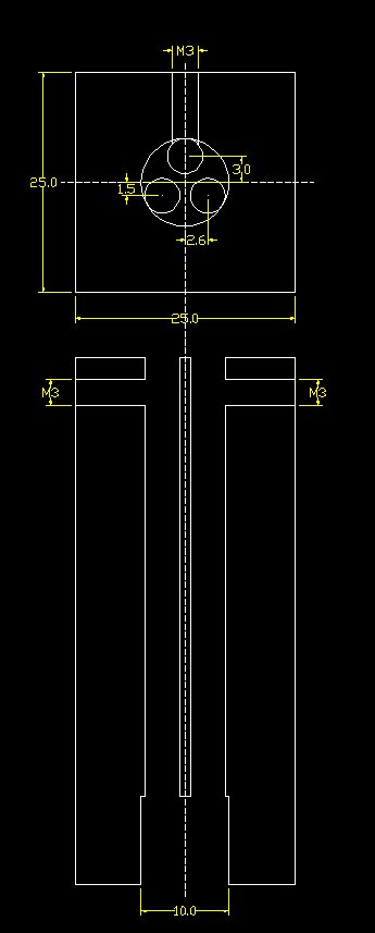
The drawing of the High Voltage Connector.