The Safety Board monitors and controls most of the system.
The board contains an Arduino MEGA2560 which communicates with the Pi via an Ethernet Shield using the UDP-protocol.
Communicaion with the Winch Controller (WCB) uses a serial port.
The board is built on a standard EuroCard (100 x 160 mm) format experimenting board. The hand wiring was done with insulated copper wire, the type where the insulation disappears at soldering temperature.
See the schematic in PDF.
See the Layout in PDF. The board was not routed. The layout was used for placing components an hand-wiring the board.
[Photograph]
See the document with the Pin-use and the Messages exchanged.
To make the connctions to this board we had some very nice connectors available, ripped from some other board in our storage. See photo.
These connectors allowed lots of GND terminals, so we could avoid to have many wires in one terminal.
Also the terminals were consecutively numbered which made it easy to find the right terminal.
Most digital inputs have explicit pull-up resistors, the arduino's internal pull-ups are a bit weak, around 40 kOhm. We do use the internal pull-up's, because some tests were to be done on an almost bare Arduino Mega, and there you want to have the inputs defined.
Most inputs were also filtered to make them more immune to HF noise.
Most outputs go throug some kind of driver, 7 go through a ULN2003 which has open collector outputs allowing up to 50 Volts and 500 mA current.
Outputs which switch mains voltage go through Solid-State switches. See the Crydom Board.
Analog inputs.
We have a quite accurate voltage reference in the LM317. It gives 2.5 Volts. We use it to determine the supply voltage of the arduino, which is the reference for other voltage measurements.
To measure the PWM percentage of the laser power input on the High Voltage PSU we filter with a second-order low-pass filter. However, our measurement relates to the Arduino's 5-Volt supply, not the 5-V on the HVPSU. For that reason we also measure the 5-Volt from the HVPSU, and do some calculations.
The Laser Tube Voltage is measured with the help of a resistor chain, consisting of 70 resistors of 10 MegOhm. With 100 kOhm as foot-resistor and a ADC range of 5 Volt we can measure up to 35 kV. The resistor chain is housed in a silicone tube, with an extra insulating tube on the high-voltage end.
The Laser Tube Current is measured using a shunt resistor of 140 Ohm, giving a range of 35 mA at 5V ADC range.
Measuring the conductivity of the coolant is described here. Note that the sensing input T69 is kept on average half Arduino-VCC. The squarewave drive signal on T71 also is half-VCC on average, so the sensor module carries no DC.
Laser Mode switching:
On the GUI one can choose between Power mode By-Job, Manual or No Laser Power.
In the By-Job mode the PWM signal from the SMB is routed to the HVPSU and measured via the T75 input. For the Manual mode a relay is engaged which switches to a local PWM signal, in stead of that from the SMB. In both cases the %Power indicator on the GUI shows the actual value going to the HVPSU. In the No-Laser Power mode the Enable_Laser signal on T1 is not activated.
See also the Laser Interface page.
Temperature measurements are done with the well known DS1820 Ic's using the One-Wire library. We do supply the ICś with +5 Volt because I found earlier that phantom supply did not always work reliable.
The ID button is also read by the OneWire library, but on a different Arduino pin. The ID button does not allow other devices on the bus.
Ethernet communication is done with a separate ETH module connected to the SPI-bus. Initially a cheap W5500 module was used, because using a regular ETH shield conflicted with the board layout. However we experienced a serious EMC problem with this module, switching noise on a mains cable often disabled the communication. In the end we did manage to connect a "official" Ethernet Shield and from then on these EMC problems were gone.
A very helpfull tool for EMC testing is an ordinary piezo-electric gas lighter, preferably one without gas. The sparks (do not spark on the electronic circuits themselves, only in the vicinity) are strong enough to disrupt the functioning of equipment when it is not EMC-proof.
In many EMC-labs the "gas lighter test" is used to fast determine if equipment is likely to pass the official regulatory tests or likely not.
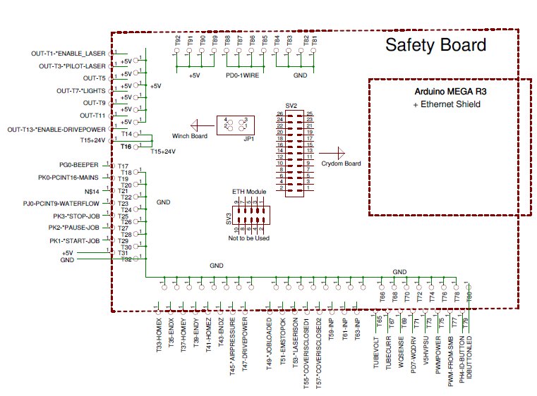
Safety Board Connections. Download as .PDF