Connections
Besides the Home signals of axis X, Y and Z the SMB receives from the SFB the signals “Start Job”, “Pause Job” and “Stop Job”, and sends the signal “Job Loaded” to the SFB. To control the Laser tube the SMB sends the signals “Laser On” and “Laser PWM” to the HVPSU*. The SFB decides whether the HVPSU is enabled, using the “Water Protect” input of the HVPSU.
Also see the Laser Interface page.
Serial Communication:
SmoothieBoard (SMB) uses TX0 and RX0 to communicate with the LaserWeb Server on the PI on /dev/ttyAMA0 on the GPIO connector.
An almost 1:1 flatcable provides the connection. See below.
Home swiches:
X- (left) on P1.29
Y- (front) on P1.27
Z+ (bottom) on P1.24
Switch hit = switch open = high = 5V. Why? The most likely fail mechanism is a loose wire, which will produce a safe condition.
SMB does not monitor the End switches.
X, Y and Z steppers:
Only Step and Dir are used. Enable is not used.
Signals go through a ULN2003 to the stepper drives, so are inverted.
Signal "JobLoaded" from SMB to SafetyBoard (SFB) via ULN2003, so inverted.
Make this true (high, after ULN low) when a Job has been loaded into the SmoothieBoard.
Make it false (low) when the Job is Stopped or no job has been loaded yet.
Note: when a job is finished this signal must go false for 1 second and return to true to allow a restart.
SFB will check the system and if OK enables the Start button on the GUI.
SFB assumes a job running when a job has been loaded and the user has pressed START.
SFB assumes a job finished when JobLoaded went false for 1 second or longer, or when StopJob has been pressed.
A new job can not be loaded from LaserWeb if a job is running or paused. If it is paused one should first stop it on the GUI.
Signal "StartJob" from SFB to SMB, OC output, so active low:
If StartJob goes true (low) start a newly loaded job or restart an already loaded job that has finished.
StartJob will not go true while a job is running, but SMB should ignore it when a job is running.
Signal "Pause" from SFB to SMB, OC output, so active low:
If Pause goes true: (active low) finish current movement, then stop.
While Pause is true: no job can be loaded.
If Pause goes false: Continue Job.
While Pause is false: a new job can be loaded if a previous job is finished or Stopped.
Pause originates from a user action on the GUI, or when the tube temperature becomes to high.
Initially Pause is false.
When a job is finished the user can restart it with the Start button.
Signal "StopJob" from SFB to SMB, OC output, so active low:
If StopJob goes true: (active low) immediately stop the running job, do not unload it (the user might want to restart the job),
StopJob originates from a user action on the GUI and the user must confirm it with an extra action. StopJob lasts one second, then returns to false.
Signal "LaserON" from SMB to HVPSU
SFB monitors this signal for calculating the LaserON-time.
LaserON is activive high and goes through the ULN2003 for active-low on HVPSU.
Note: This signal OC to allow a wired OR on the SFB for test-shooting.
Note: "Laser Enable" is given by SFB upon a user action on the GUI. This allows a job te be run without actual lasering.
Signal "LaserPWM" from SMB to HVPSU, OC output, so active low:
SFB monitors this signal to indicate it on the GUI.
Active low (OC output high), e.g. +5V is full power, 50% PWM is half power.
PWM frequency must be > 20 kHz.
In case of manual Power% the SFB provides the PWM to the HVPSU
Smoothie Interface Board
We have an interface board as a piggyback on the SMB, making use of the fact that the 5 headers with the stepper signals are on a 0.1" pitch.
We do not use the Enables for the steppers and we do not use the 2 Extruder steppers, so we have 9 I/O pins available there.
On the interface board a ULN2003 will interface the stepper signals and an octal HC chip will buffer the other signals.
We do not like to go into the machine wiring with wires directly connected to the CPU.
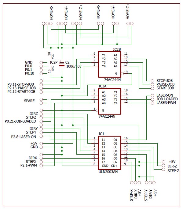
Smoothie Board Interface.
The SMB is supplied with +5V from the Interface board, via the Home connectors (upper left).
The stepper signal go through the ULN2003 Open-collector buffer, the Job-signal are buffered by the 244 buffer, except the Laser-ON signal which is alse bufferd by the ULN, to allow wired-or on the SFB, to do Test-shooting.
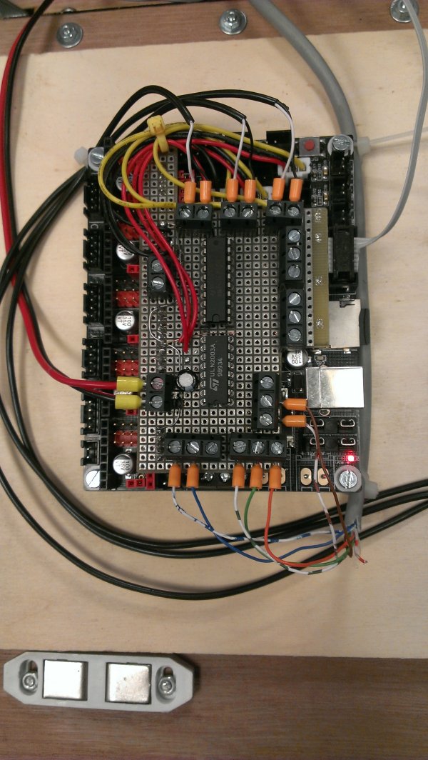
Smoothie Board with the Interface piggy-back.
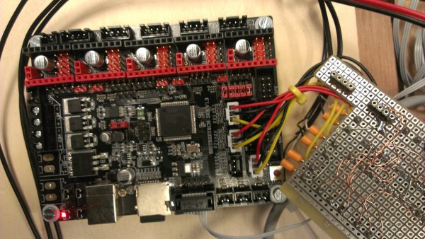
The Interface Board detached from the SMB.
The quite high power connectors were removed from the SMB.
Pin use: (all these pins are 5V tolerant)
LaserPWM: EnableX = P2.1 as output from PWM modulator 1, channel 2
JobLoaded: EnableY = P2.8 as output, active low,
LaserON: EnableZ = P0.21 as output, active high, after ULN active low
StartJob: EnableE0 = P2.12 as input, active low.
PauseJob: StepE0 = P2.13 as input, active low.
StopJob: DirE0 = P0.11 as input, active low.
spare1: EnableE1 = P0.10
spare2: StepE1 = P0.1
spare3: DirE1 = P0.0
Configuration
[ Settings like polarity of home-switches, directions of movements, homing procedure, etc ]
[ Probably also machine specific settings for LaserWeb Server ]
Modifications
In the software on the SMB several modifications were made by BugBlue*. The processing of G-codes was modified such that movement trajectories are extended with a lead-in and a lead-out part, causing the movement to be on the specified speed when the target location is reached. This prevents burned corners or to heavy burning at the beginnings and ends of raster lines due to the movement still being in the accelleration stadium.
These modifications are described an motivated below:
[ text to be produced by Bug ]
Serial Cable
The cable between the SMB and the Pi is a bit tricky but it can be done with a piece of flatcable, and a 2x2 and a 2x4 flatcable connector:
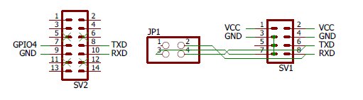
Serial Cable between SMB and PI.
On the left we see a part of the Pi's GPIO connctor. Pins 8 and 10 are TXD and RXD
On the right we see the pinning on the SMB. On the bottom of the SMB we connect pins 3-5-7 by solder lumps.
We start with a 8-wire flatcable on the SMB side and cut the wires 1, 2, 3, 4 and 5.
We twist the remianing 3 wire cable and squeeze it into the 2x2 connector, but leave pin 1 unconnected.
On the Pi we need to cut the pins 5, 6, 11 and 12 to make room for JP1. Note that TXD and RXD must be crossed.
We need to configure the Pi such that the serial port /dev/ttyAMA0 is enabled, but not for tty-login and that the user is member of the group dialout.